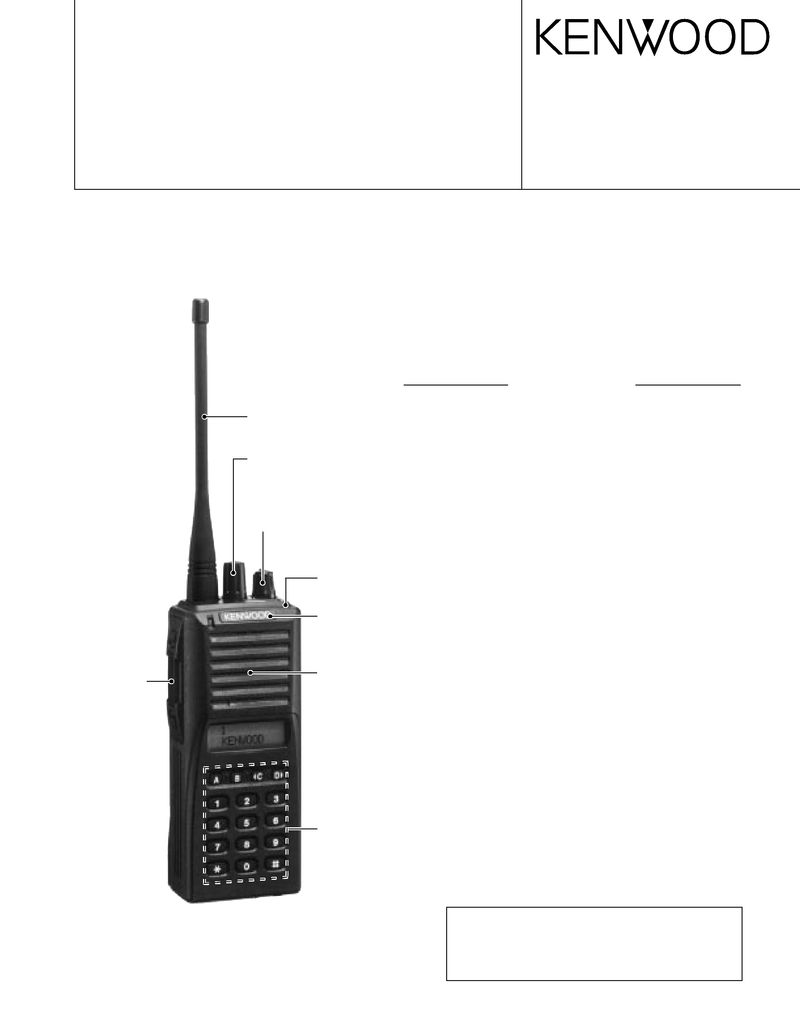
KENWOOD TK380 Service Manual

Cover page of KENWOOD TK380 Service Manual

Service Manual for KENWOOD TK380, downloadable as a PDF file.

We also have owner's manual to this model.

Manual details

  • Immediate download after payment.
  • Delivered as a PDF file.
  • The manual has 66 pages
  • File size: 3.93 MB
  • Available language versions: English
  • Different language versions may vary sligthly in file size and page count.

We guarantee that...

  • our manuals are complete,
  • the manual includes circuit diagrams,
  • our manuals are checked with antivirus,
  • We'll issue refund if the manual is damaged, incomplete or unreadable (our refund policy)

Sample pages

Thumbnail of page 1Thumbnail of page 2Thumbnail of page 3Thumbnail of page 4
Thumbnail of page 5Thumbnail of page 6Thumbnail of page 7Thumbnail of page 8
Thumbnail of page 9
background image
UHF FM TRANSCEIVER
TK-380
© 2000-4 PRINTED IN JAPAN
B51-8522-00(S) 553
SERVICE MANUAL
GENERAL ................................................................................. 2
SYSTEM SET-UP ..................................................................... 2
OPERATING FEATURES ......................................................... 3
REALIGNMENT ...................................................................... 16
CIRCUIT DESCRIPTION ........................................................ 20
SEMICONDUCTOR DATA ..................................................... 26
DESCRIPTION OF COMPONENTS ....................................... 32
PARTS LIST ............................................................................ 33
EXPLODED VIEW .................................................................. 42
PACKING ................................................................................ 43
ADJUSTMENT ........................................................................ 44
TERMINAL FUNCTION .......................................................... 56
PC BOARD VIEWS
DISPLAY UNIT (X54-3210-12) .......................................... 57
TX-RX UNIT (X57-6200-XX) ............................................. 63
SCHEMATIC DIAGRAM ......................................................... 69
BLOCK DIAGRAM .................................................................. 73
LEVEL DIAGRAM ................................................................... 75
OPTIONS ................................................................................ 76
SPECIFICATIONS ............................................... BACK COVER
CONTENTS
Knob (ENC)
(K29-5232-03)
Knob (VOL)
(K29-5231-03)
Cabinet assy
(A02-2055-53)
(16 keys)
Badge
(B43-1106-14)
Packing
(G53-0896-02)
(16 keys)
Panel assy
(A62-0535-04)
Knob (PTT etc)
(K29-5157-03)
Whip antenna
(T90-0682-05):E
(T90-0684-05):E3
CAUTION
When using an external power connector,
please use with maximum final module
protection of 9V.
Photo is E type with KRA-15
E VERSIONS
background image
TK-380
2
GENERAL / SYSTEM SET-UP
INTRODUCTION
SCOPE OF THIS MANUAL
This manual is intended for use by experienced technicians
familiar with similar types of commercial grade communications
equipment. It contains all required service information for the
equipment and is current as of the publication data. Changes
which may occur after publication are covered by either Service
Bulletins or Manual Revisions. These are issued as required.
ORDERING REPLACEMENT PARTS
When ordering replacement parts or equipment information,
the full part identification number should be included. This
applies to all parts : components, kits, or chassis. If the part
number is not known, include the chassis or kit number of which
it is a part, and a sufficient description of the required
component for proper identification.
PERSONNEL SAFETY
The following precautions are recommended for personnel
safety:
q
DO NOT transmit until all RF connectors are verified secure
and any open connectors are properly terminated.
q
SHUT OFF and DO NOT operate this equipment near
electrical blasting caps or in an explosive atmosphere.
q
This equipment should be serviced by a qualified technician only.
SERVICE
This radio is designed for easy servicing. Refer to the
schematic diagrams, printed circuit board views, and alignment
procedures contained within.
NOTE
The terms "Wide" and "Semi wide" used in this service
manual correspond to "Wide 5K" and "Wide 4K" respectively
that appear in the menu and help texts of the KPG-60D (Field
Programming Unit).
Unit
X57-620X-XX X54-321X-XX
5TONE/DTMF/DMS
Model &
Frequency range
Remarks
QT/DQT
or
Charger Battery
destination
0-10
0-11
0-12
2TONE(Decode only)
TK-380
E
440~470MHz
IF1 : 44.85MHz
OP
OP
E3
406~450MHz
LOC : 44.395MHz
Merchandise received
Choose the type of transceiver
Transceiver programming
Delivery
Are you using the speaker microphone?
TX/RX 440~470
4.0W
TK-380 E
TX/RX 406~450
4.0W
TK-380 E3
Frequency range (MHz) RF power
Type
A personal computer (IBM PC or compatible), programming
interface (KPG-36), and programming software (KPG-60D)
are required for programming.
(The frequency, conventional system features, TX power HI/LOW,
and signalling data are programmed for the transceiver.)
YES
NO
KMC-25
Speaker microphone
(Option)
SYSTEM SET-UP
background image
TK-380
3
OPERATING FEATURES
1. Operation Features
The TK-380 is a UHF FM Radio designed in both 5tone
Model and DTMF/2tone/DMS Model. The programmable
features are summarized.
This transceiver can handle up to 250 groups with 250
channels in each group.
Model
5Tone
Basic
Full
Full (Special Setting)
DTMF/2tone/DMS
1-1. 5tone Model
In this model, you can program Basic or Full level features.
When you select Basic level, only 1frame 5tone can be
programmed, and various functions are limited.
When you select "Special setting" in the Full Level, you can
use Encode/Decode format. Using Encode/Decode format, you
can further program the transceiver to run the script.
1-2. DTMF/2tone/DMS Model
You can use Option signalling which is DTMF or 2tone(only
for Decode) or DMS(Digital Message System -FFSK signalling)
for every channel.
2. Transceiver Controls and Indicators
2-1. Physical Layout
Note: The transceiver is also available without the DTMF
keypad (-).
2-2. Panel controls
The key on the top and front panel is momentary-type push
buttons. The functions of these keys and knob are explained
below.
1 Antenna connector
Connect the supplied antenna here.
2 Group or Channel selector knob (Programmable)
Turning the group (or channel) selector knob clockwise
increases the group (or channel) number by one. Turning
the knob in the counterclockwise direction decreases the
group (or channel) number by one.
After the group number (or channel number) reaches the
highest group number (or channel number), it goes back to
lowest group number (or channel number).
Group numbers (or channel numbers) not set are skipped.
Caution : The FPU (KPG-60D) allows selecting between
group selector and channel selector.
3 Volume/Power switch
Transceiver Power and Volume switch. Turn clockwise to
switch On the transceiver. Turn counterclockwise fully to
switch OFF the transceiver. Also adjusts the volume level.
When the power is switched off, all the parameters, such
as the group and channel, are stored in memory. When the
power is switched on again, the group returns to the previous
conditions.
4 Auxiliary (orange) key (Programmable)
5 Battery pack release catch
Push down to release the battery pack. See Installing the
Ni-Cd Battery Pack.
6 MONITOR key* (Programmable)
7 PTT (Push-To-Talk) key
Press this key, then speak into the microphone to call a
station.
8 CALL key* (Programmable)
9 TX/BATT indicator
This red LED lights during transmission (it does not light
during busy or when transmit is prohibited). If the battery
voltage falls below the programmed voltage during
transmission, the brightness of this indicator decreases at
intervals of about one second, so it can be used as the
battery voltage alert function.
0 A, B,
2 C, and D 3 key (Programmable)
- DTMF keypad (keypad model only)
Press the keys on the telephone keypad to send DTMF
tones.
= Universal connector
Connect the external KMC-25 speaker/ microphone
(optional) here. Otherwise, keep the supplied cover in place.
* : MONITOR and CALL are arbitrary names chosen for
these buttons. They can be used for any of the auxiliary
functions.
background image
TK-380
4
OPERATING FEATURES
2-3. Programmable keys
The FPU (KPG-60D) enables programmable keys to select
the following functions.
Function
DTMF/2tone/DMS Model
5tone Model
note
None
Yes
Yes
Auto Dial
Yes
Yes
Auto Dial Programming
Yes
Yes
AUX B
Yes
Yes
Only when voice scrambler is not selected
Call 1
No
Yes
Call 2
No
Yes
Call 3
No
Yes
Call 4
No
Yes
Call 5
No
Yes
Call 6
No
Yes
Channel Down
Yes
Yes
Channel Entry
Yes
Yes
Channel Name
Yes
Yes
Channel Up
Yes
Yes
Emergency Call
Yes
Yes
Fixed Volume
Yes
Yes
Group Down
Yes
Yes
Group Up
Yes
Yes
Home Channel
Yes
Yes
Key Lock
Yes
Yes
Lamp
Yes
Yes
Low Power
Yes
Yes
Monitor
Yes
Yes
Monitor Momentary
Yes
Yes
Operator Selectable Tone
Yes
Yes
Queue
Yes
Yes
Radio Password
Yes
Yes
Receive Entry
No
Yes
Scan
Yes
Yes
Scan Delete/Add
Yes
Yes
Scrambler
Yes
Yes
Selcall Entry
Yes
Yes
Selcall List
Yes
Yes
Selcall+Status Entry
Yes
Yes
Selcall+Status List
Yes
Yes
Shift
Yes
Yes
Squelch Level
Yes
Yes
Squelch Momentary
Yes
Yes
Squelch Off
Yes
Yes
Status Entry
No
Yes
Status List
No
Yes
Talk Around
Yes
Yes
Channel Up/Down
Yes
Yes
Group Up/Down
Yes
Yes
background image
TK-380
5
OPERATING FEATURES
s Auto Dial
To transmit the stored DTMF code automatically.
When you select DTMF Encode in the "Auto Dial Mode"
menu, Auto Dial, Re-Dial, Dial ID and Store & Send modes
are available.
Press the [Auto Dial] key to enter the "Auto Dial Mode".
Select the desired number to send. It is used the Selector
or the [2] and [8] keys to select.
Press the [*] key to transmit the numbers.
s Auto Dial Programming
You can store the DTMF code and Name, or erase it at the
transceiver.
q
To store a DTMF code:
Press the [Autodial Programming] key to enter "Autodial
Programming Mode". Select the desired memory number
you wish to store.
Press the [*] key to select the desired memory number(Enter
Autodial Memory Name).
Press the [*] key to store the Memory Name. Now, enter
the DTMF codes you want to store.
Press the [*] key to store the numbers.
A beep sound confirms that the numbers are stored in the
memory.
q
To erase the stored DTMF Code:
Press the [Autodial Programming] key to enter Autodial
Programming mode.
Press the [#] key to enter Auto Dial Clear mode. Select the
Memory Number you want to erase.
Press the [*] key to erase the stored numbers and exit Auto
Dial Clear mode.
s AUX B
This function can be programmed when the voice scrambler
board is not installed.
If this key is pressed, an underscore ("_") appears at the
extreme right of the LCD and OPT port which is inside of the
transceiver turns to the active level(Low). If pressed again, the
underscore disappears and the OPT ports turns to the deactive
level(High).
s Channel Name
Press this key to switch between the "Channel Name" and
"Grp#/Ch#" for the display. If no channel name is programmed,
the transceiver automatically displays the group#/channel#.
s Channel Up/Down
When this key is pressed each time, the channel number to
be selected is increased/decreased and repeats if held for one
second or longer.
s Call 1 to 6 (5tone)
Press the [CALL #] key to transmit the 5tone code that is
programmed to "Call #" in the System Parameters.
s Channel Entry
You can directly recall the channel using the numeric keypad
without using the [Channel Up/ Down].
To access the channel directly, enter 1 to 3 digit numbers,
depending on the number of the programmed channels.
For example, if the radio has 199 programmed channels
(the maximum channel number is a 3-digit number) and you
would like to recall channel 5, you must enter [0], [0], [5]. If the
radio has 99 channels (2-digit number), you must enter [0], [5]
to access channel 5.
s Emergency Call
Pressing this key causes the transceiver to enter the
emergency mode. The transceiver jumps to the programmed
"Emergency group/channel" and transmits for programmed
"Duration of Transmission time".
The transceiver disables mic mute while transmitting. After
finishing transmission, the transceiver receivers for
programmed "Duration of Receiving". The transceiver mutes
the speaker while receiving. Following the above sequence,
the transceiver continues to transmit and receive.
You can select whether or not the emergency ID is
transmitted in the emergency mode.
s Fixed Volume
This function is used for changing the volume level, it is
Power on Tone, Control Tone, Warning Tone, Alert Tone, AF
Volume Type.
If these Tone is set up in "Fixed", the Tone level can be
changed when [Fixed Volume] key is pressed.
When [Fixed Volume] key is pressed, Tone level changes
in turn to Low(Tone Volume Low), High(Tone Volume High)
and Off.
s Group Up/Down
When this key is pressed each time, the group number to
be selected is increased/decreased and repeats if held for one
second or longer.
s Home Channel
Press this key once, the channel switches to the pre-
programmed home channel.
s Key Lock
Key Lock prevents accidental operation of the transceiver.
When Key Lock is activated, all keys other that PTT,
Emergency, Monitor, Monitor Momentary, Shift, Squelch,
Squelch Momentary, Lamp, Volume are locked.
"LOCKED" appears momentarily when the Key Lock key is
pressed.

Reviews

There are no reviews of this manual yet.