2
TK-3107
MODE
FUNCTION
User Mode
Use this mode for normal operation.
PC Mode
Use this mode, to make various
settings by means of the FPU through
the RS-232C port.
Manufacture Mode Use this mode, to realign the various
settings through the RS-232C port
during manufacture work.
2 How to enter each mode
MODE
PROCEDURE
User Mode
Power ON
PC Mode
Connect to the IBM PC compatible
machine and controled by the FPU.
1 Modes
INTRODUCTION
SCOPE OF THIS MANUAL
This manual is intended for use by experienced technicians
familiar with similar types of commercial grade
communications equipment. It contains all required service
information for the equipment and is current as of the
publication data. Changes which may occur after publication
are covered by either Service Bulletins or Manual Revisions.
These are issued as required.
ORDERING REPLACEMENT PARTS
When ordering replacement parts or equipment
information, the full part identification number should be
included. This applies to all parts : components, kits, or
chassis. If the part number is not known, include the chassis or
kit number of which it is a part, and a sufficient description of
the required component for proper identification.
PERSONAL SAFETY
The following precautions are recommended for personal
safety :
· DO NOT transmit until all RF connectors are verified secure
and any open connectors are properly terminated.
· SHUT OFF and DO NOT operate this equipment near
electrical blasting caps or in an explosive atmosphere.
· This equipment should be serviced by a qualified
technician only.
SERVICE
This radio is designed for easy servicing. Refer to the
schematic diagrams, printed circuit board views, and
alignment procedures contained within.
GENERAL/REALIGNMENT
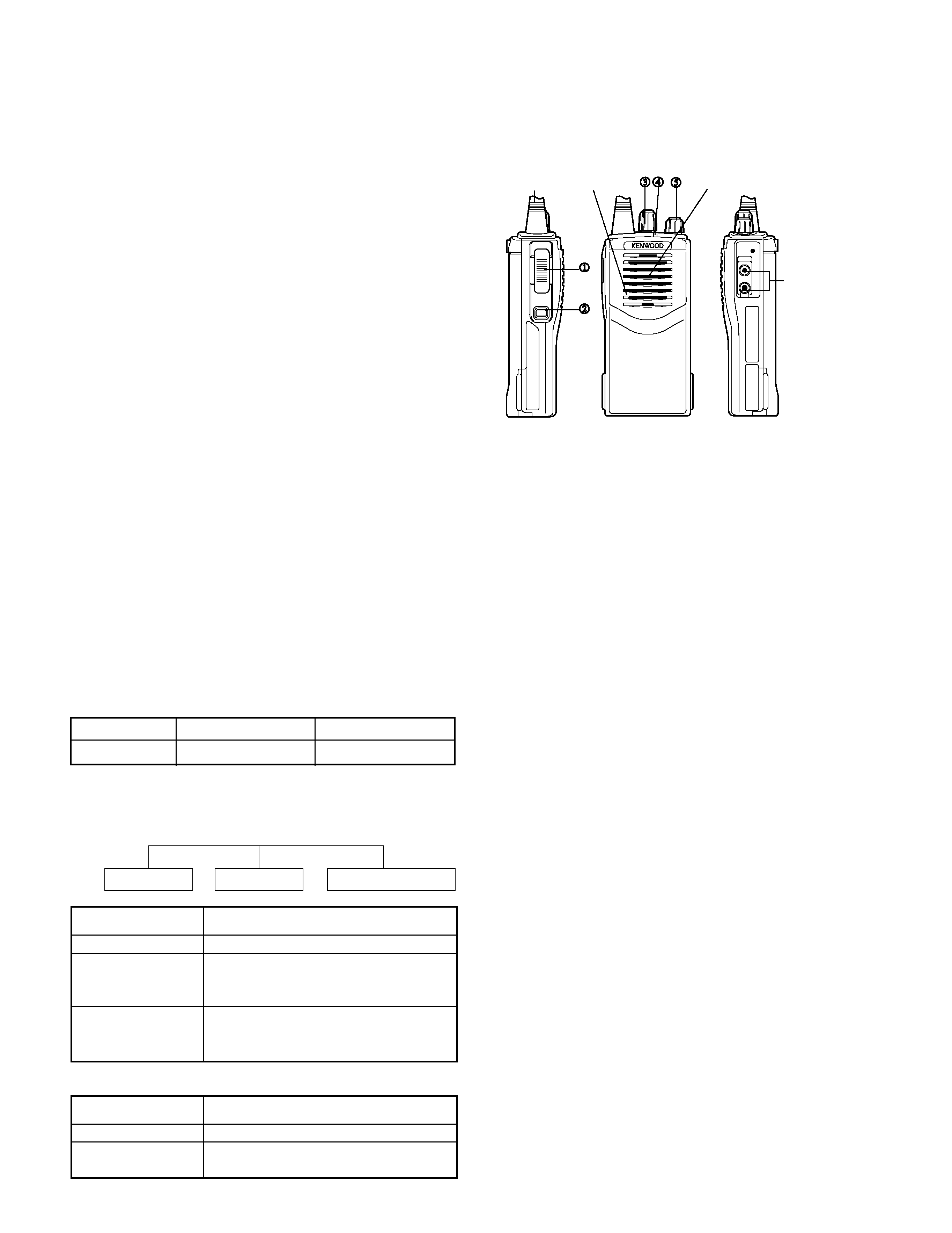
3 Getting acquainted
PC Mode
User Mode
Manufacture Mode
Destnation
Number of CH
RF power output
M2
16
4W
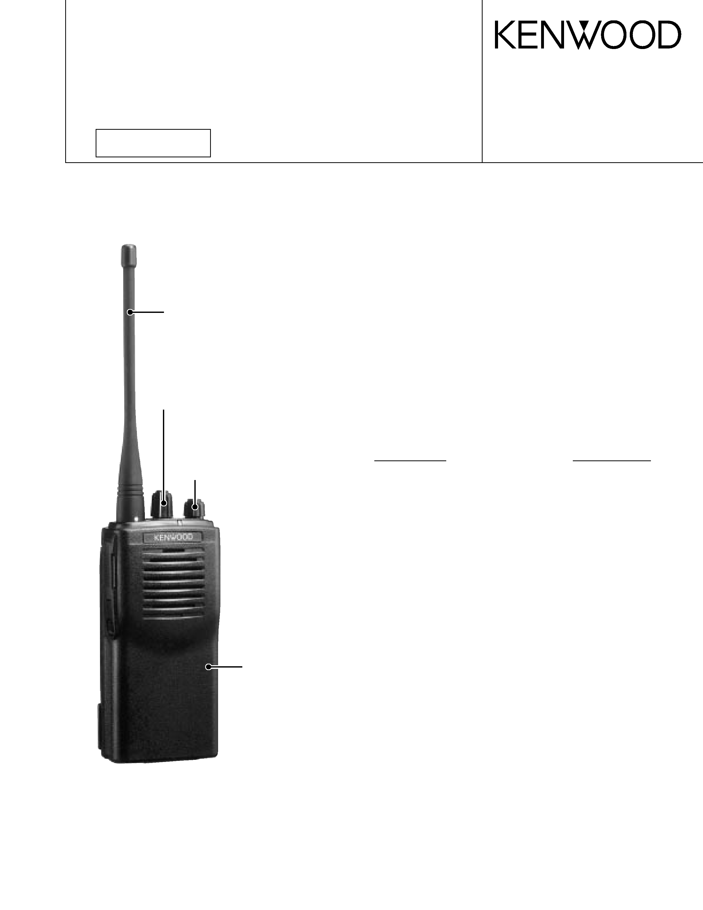
Speaker
Antenna
Speaker/
microphone
jacks
Microphone
x PTT (Push-To-Talk) switch
Press this switch, then speak into the microphone to
call a station. Release the switch to receive.
y Monitor key
Press and hold to monitor how busy the current
channel is and to monitor signals being received that
do not contain the matched QT/DQT code.
z Channel selector
Rotate to select channels 1 ~ 16.
LED indicator
Lights red while transmitting, green while receiving a
signal. Flashes red when the battery voltage is low
while transmitting.
| Power switch/ Volume control
Turn clockwise to switch the transceiver ON. Turn
counterclockwise until a click sounds, to switch the
transceiver OFF. Rotate to adjust the volume level.
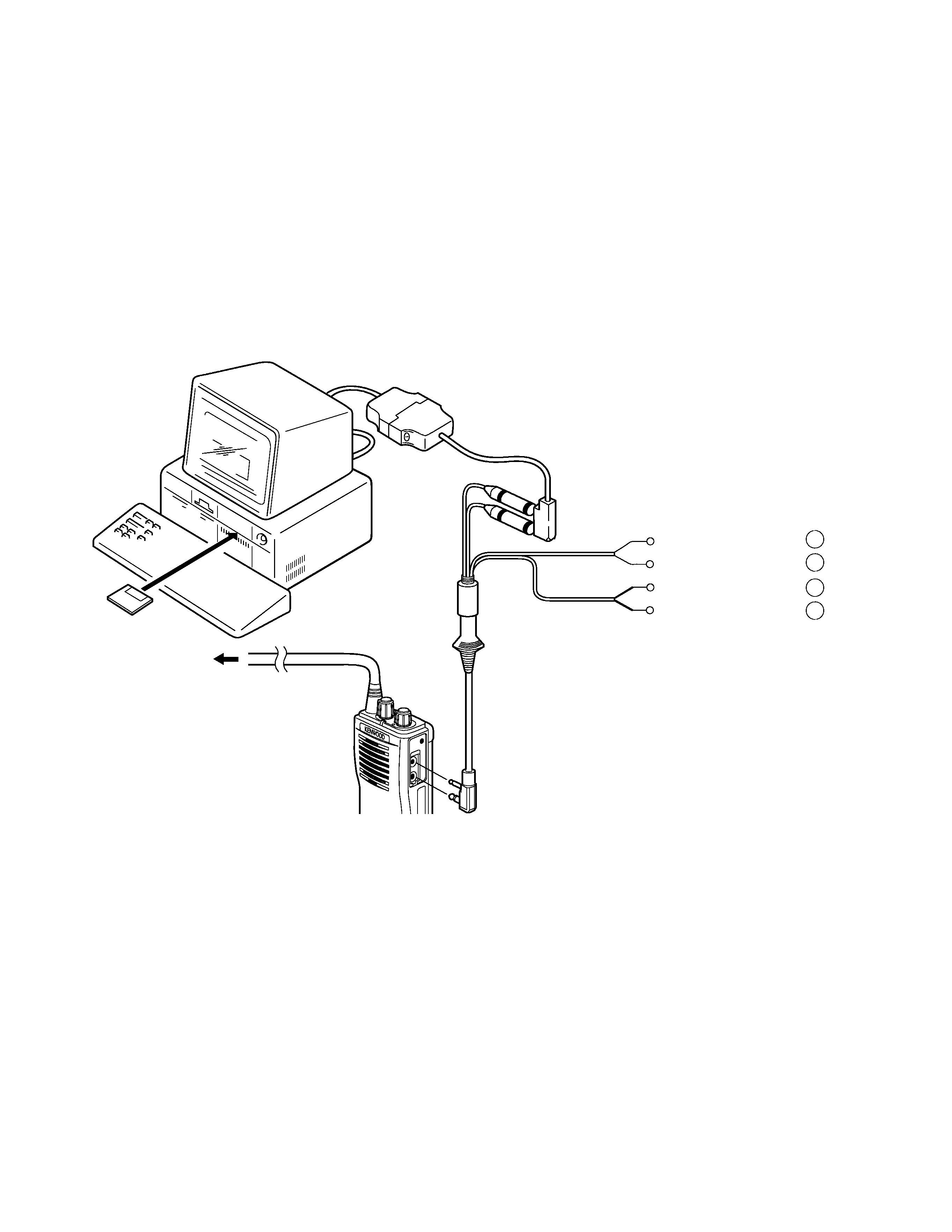
PC MODE
Preface
The transceiver is programmed by using a personal
computer, programming interface (KPG-22) and programming
software (KPG-55D).
The programming software can be used with an IBM PC or
compatible. Figure 1 shows the setup of an IBM PC for
programming.
Connenction procedure
1. Connect the TK-3107 to the personal computer with the
interface cable.
2. When data is transmitting from the transceiver the red LED
lights.
When data is received by the transceiver the green LED
lights.
Notes:
· The data stored in the personal computer must match the
Model Name when it is written into the EEPROM.
· Do not press the [PTT] key during data transmission or
reception.
REALIGNMENT