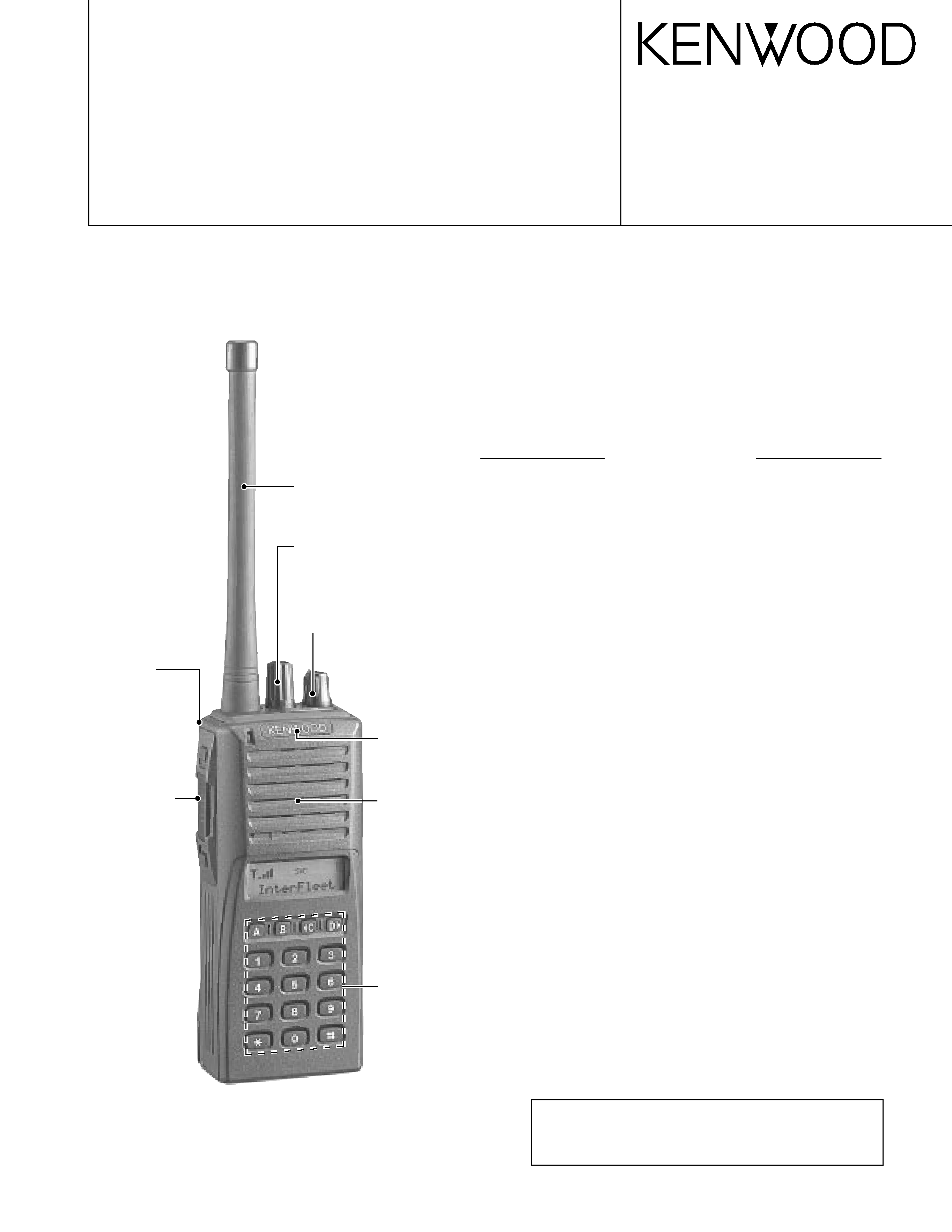
KENWOOD TK285N Service Manual

Cover page of KENWOOD TK285N Service Manual

Service Manual for KENWOOD TK285N, downloadable as a PDF file.

Manual details

  • Immediate download after payment.
  • Delivered as a PDF file.
  • The manual has 42 pages
  • File size: 3.28 MB
  • Available language versions: English
  • Different language versions may vary sligthly in file size and page count.

We guarantee that...

  • our manuals are complete,
  • the manual includes circuit diagrams,
  • our manuals are checked with antivirus,
  • We'll issue refund if the manual is damaged, incomplete or unreadable (our refund policy)

Sample pages

Thumbnail of page 1Thumbnail of page 2Thumbnail of page 3Thumbnail of page 4
Thumbnail of page 5Thumbnail of page 6Thumbnail of page 7Thumbnail of page 8
Thumbnail of page 9
background image
VHF FM TRANSCEIVER
TK-285/(N)
© 2000-6 PRINTED IN JAPAN
B51-8530-00(S) 847
SERVICE MANUAL
GENERAL ................................................................................. 2
SYSTEM SET-UP ..................................................................... 2
OPERATING FEATURES ......................................................... 3
REALIGNMENT ........................................................................ 4
CIRCUIT DESCRIPTION .......................................................... 6
SEMICONDUCTOR DATA ..................................................... 11
DESCRIPTION OF COMPONENTS ....................................... 13
PARTS LIST ............................................................................ 14
EXPLODED VIEW .................................................................. 22
PACKING ................................................................................ 23
ADJUSTMENT ........................................................................ 24
TERMINAL FUNCTION .......................................................... 32
PC BOARD VIEWS
DISPLAY UNIT (X54-3210-13) ............................................ 33
TX-RX UNIT (X57-619X-XX) ............................................... 39
SCHEMATIC DIAGRAM ......................................................... 45
BLOCK DIAGRAM .................................................................. 49
LEVEL DIAGRAM ................................................................... 51
OPTIONS ................................................................................ 52
SPECIFICATIONS ............................................... BACK COVER
CONTENTS
CAUTION
When using an external power connector, please use
with maximum final module protection of 9V.
Photo is K type
Knob (ENC)
(K29-5232-03)
Knob (VOL)
(K29-5231-03)
Cabinet assy
(A02-2055-53)
(16 keys)
Badge
(B43-1106-14)
Packing
(G53-0896-02)
(16 keys)
Panel assy
(A62-0535-04)
Helical antenna
(T90-0733-05):K, E
(T90-0734-05):(N)M
Knob (PTT etc)
(K29-5157-03)
background image
TK-285/(N)
2
GENERAL / SYSTEM SET-UP
Unit
Model &
TX-RX unit
Display unit
Frequency range
Remarks
Charger
Battery
destination
K
X57-6190-11
RX : 217~250MHz
IF1 : 44.85MHz
OP
TK-285
E
X54-3210-13 TX : 218~250MHz
LOC : 44.395MHz
OP
(N)M
X57-6190-21
240~270MHz
Merchandise received
Choose the type of transceiver
Transceiver programming
Delivery
Are you using the speaker microphone?
TX 218~250
RX 217~250
5.0W
TK-285 K,E
TX/RX 240~270
5.0W
TK-285 (N)M
Frequency range (MHz) RF power
Type
A personal computer (IBM PC or compatible), programming
interface (KPG-36), and programming software (KPG-62D)
are required for programming.
(The frequency, conventional system features, TX power HI/LOW,
and signalling data are programmed for the transceiver.)
YES
NO
KMC-25
Speaker microphone
(Option)
SYSTEM SET-UP
INTRODUCTION
SCOPE OF THIS MANUAL
This manual is intended for use by experienced technicians
familiar with similar types of commercial grade communications
equipment. It contains all required service information for the
equipment and is current as of the publication data. Changes
which may occur after publication are covered by either Service
Bulletins or Manual Revisions. These are issued as required.
ORDERING REPLACEMENT PARTS
When ordering replacement parts or equipment information,
the full part identification number should be included. This
applies to all parts : components, kits, or chassis. If the part
number is not known, include the chassis or kit number of which
it is a part, and a sufficient description of the required
component for proper identification.
PERSONNEL SAFETY
The following precautions are recommended for personnel
safety:
q
DO NOT transmit until all RF connectors are verified secure
and any open connectors are properly terminated.
q
SHUT OFF and DO NOT operate this equipment near
electrical blasting caps or in an explosive atmosphere.
q
This equipment should be serviced by a qualified technician
only.
SERVICE
This radio is designed for easy servicing. Refer to the
schematic diagrams, printed circuit board views, and alignment
procedures contained within.
OP
background image
TK-285/(N)
3
OPERATING FEATURES
1. Operation Features
The TK-285 is a VHF FM Radio designed in both Trunking
Mode and Conventional Mode.
2. Transceiver Controls and Indicators
2-1. Physical Layout
2-2. Panel controls
The key on the top and front panel is momentary-type push
buttons. The functions of these keys and knob are explained
below.
1 Antenna connector
Connect the antenna here.
2 Rotary encoder
3 POWER switch/ VOLUME control
Turn clockwise to switch ON the transceiver. Rotate to
adjust the volume. Turn conterclockwise fully to switch OFF
the transceiver.
4 Auxiliary (orange) key
5 Battery pack release latch
Pull back on this latch to release the battery pack.
6 Call key
7 PTT (Push-To-Talk) switch
8 Clear key
9 Transmit/ Receive indicator
0 A key
- B key
=
2 C key
~ D
3 key
! DTMF keypad
@ Universal connector
Connect the (optional KMC-25) speaker/ microphone here.
Otherwise, keep the supplied cover in place.
2-3. Key functions
Trunking mode
2 Rotary encoder
Rotate this encoder to select your desired call address
(voice calls) ot status (status calls).
4 Auxiliary (orange) key (default setting: None)
Press to activate its auxiliary function.
6 Call key
Press to call the displayed call address.
7 PTT (Push-To-Talk) switch
Press to transmit. Also press to initiate a call if "PTT to
Initiate Call" has been programmed.
8 Clear key
Press to end the current call.
9 Transmit indicator
Lights red while transmitting.
0 A key (default setting: Status/ Stack)
Press to activate its auxiliary function.
- B key (default setting: Redial)
Press to activate its auxiliary function.
=
2 C key (default setting: None)
Press to activate its auxiliary function. Also press to scroll
left while viewing stack entries.
~ D
3 key (default setting: None)
Press to activate its auxiliary function. Also press to scroll
right while viewing stack entries.
! DTMF keypad
Press to input a call address or dialing function.
Conventional mode
2 Rotary encoder
Rotate this encoder to select your desired channel.
6 Call key
Press to turn the monitor function ON in order to monitor
your selected channel.
7 PTT (Push-To-Talk) switch
Press this switch, then speak into the microphone to call a
station.
8 Clear key
Press to return to Trunking mode.
9 Transmit/ Receive indicator
Lights green while receiving a signal. Lights red while
transmitting.
0 A key
Press to turn Scan ON (or OFF).
- B key
Press to add/delete channel(s) to/from Scan list.
~ D
3 key
Press to turn the display and keypad backlight ON.
The backlight remains ON for 5 seconds.
e
qw
r
t
o
!5
!0
!4
i
u
y
!1
!2
!3
Speaker
Microphone
background image
TK-285/(N)
4
5. PC Mode
5-1. Preface
The TK-285 transceiver is programmed by using a personal
computer, programming interface (KPG-36) and programming
software (KPG-62D).
The programming software can be used with an IBM PC or
compatible. Figure 1 shows the setup of an IBM PC for
programming.
5-2. Connection procedure
1. Connect the TK-285 to the personal computer with the
interface cable.
2. When the POWER switch on, user mode can be entered
immediately. When PC sends command the radio enter PC
mode, and "PROGRAM" is displayed on the LCD.
When data transmitting from transceiver, the red LED is
blinking.
When data receiving to transceiver, the green LED is blinking.
Notes:
·
The data stored in the personal computer must match model
type, when it is written into the flash memory.
·
Change the TK-285 to PC mode, then attach the interface
cable.
REALIGNMENT
1. Modes
Mode
Function
User mode
For normal use.
Panel test mode
Used by the dealer to check the
fundamental characteristics.
Panel tuning mode
Used by the dealer to tune the radio.
PC mode
Used for communication between the
radio and PC (IBM compatible).
Data program-
Used to read and write frequency data
ming mode
and other features to and from the radio.
PC test mode
Used to check the radio using the PC.
This feature is included in the FPU.
See panel tuning.
Firmware program-
Used when changing the main
ming mode
program of the flash memory.
User mode
Panel test mode
PC mode
Firmware
programming mode
Panel tuning mode
PC test mode
Data programming
mode
PC tuning mode
3. Panel Test Mode
Setting method refer to ADJUSTMENT.
4. Panel Tuning Mode
Setting method refer to ADJUSTMENT.
2. How to Enter Each Mode
Mode
Operation
User mode
Power ON
Panel test mode
[B]+Power ON
PC mode
Received commands from PC
Panel tuning mode
[Panel test mode]+[A]
Firmware programming mode [A]+Power ON
OPERATING FEATURES / REALIGNMENT
2-4. Display
1 Subdisplay
displays the strength of received signals.
2 Programming indicator
P appears while in AUX A or Scrambler is being activated.
3 MON (Monitor) indicator
MON appears while you are monitoring a channel by pressing
the Call key. (Conventional Mode only)
4 SVC (Service) indicator
SVC appears when a control channel is found. It flashes
while the transceiver is searching for a control channel.
5 SCN (Scan) indicator
SCN appears while you are scanning. (Conventional Mode
only)
6 LO indicator
This icon blinks while in battery warning, if "Always" or
"Always W/beep" is selected in the battery warning settings.
7 Handset indicator
flashes when you activate call diversion.
8 MAIL indicator
appears while there is data in the stack. It flashes when
there is new data in the stack.
9 Alphanumeric display
displays call addresses, the call
duration timer, data messages, and the current operating
status of the transceiver.
SVC
MON
SCN LO
12 3 4 5
9
67 8
background image
TK-285/(N)
5
REALIGNMENT
5-3. KPG-36 description
(PC programming interface cable: Option)
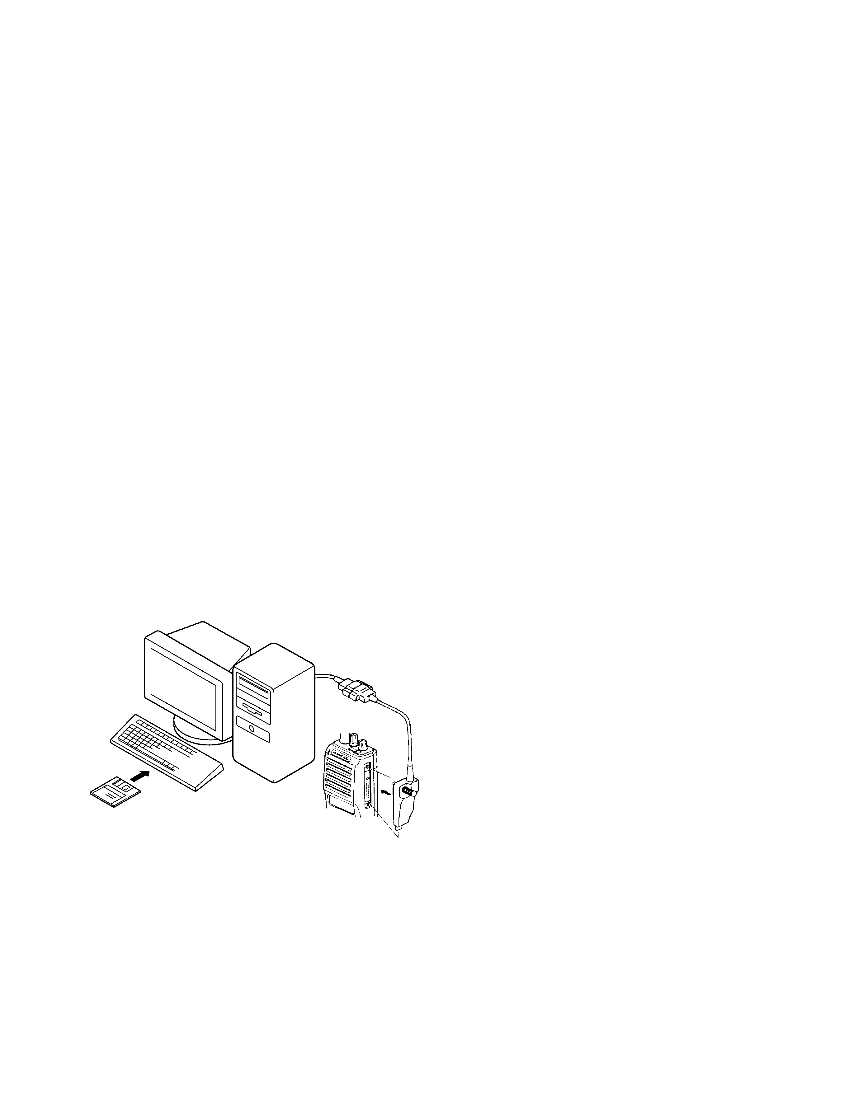
The KPG-36 is required to interface the TK-285 to the
computer. It has a circuit in its D-subconnector (25-pin) case
that converts the RS-232C logic level to the TTL level.
The KPG-36 connects the universal connector of the TK-
285 to the computers RS-232C serial port.
5-4. Programming software KPG-62D Description
The KPG-62D is the programming software for the
transceiver supplied on three 3.5" floppy disks. This software
runs under MS-Windows 95/98 on an IBM-PC or compatible
machine.
The data can be input to or read from the trnsceiver and
edited on the screen. The programmed or edited data can be
printed out. It is also possible to tune the transceiver.
We recommend that install the KPG-62D for example to
hard disk first then use it.
5-5. Programming with IBM PC
If data is transferred to the transceiver from an IBM PC with
the KPG-62D, the destination data (basic radio information)
for each set can be modified. Normally, it is not necessary to
modify the destination data because their values are
determined automatically when the frequency range (frequency
type) is set.
The values should be modified only if necessary. Data can
be programmed into the flash memory in RS-232C format via
the universal connector.
KPG-62D instruction manual parts No. : B62-1354-XX
6-3. Programming
1. Start up the firmware programming software (Fpro.exe).
2. Set the communications speed (normally, 57600 bps) and
communications port in the configuration item.
3. Set the firmware to be updated by File name item.
4. Turn the TK-285 power ON with the [A] switch held down.
Hold the switch down until the display changes to "PROG
57600". When "PROG 57600" appears, release your finger
from the switch.
5. Check the connection between the TK-285 and the personal
computer, and make sure that the TK-285 Is in the Program mode.
6. Press write button in the window. A window opens on the
display to indicate progress of writing. When the TK-285
starts to receive data. the [P] icon is blinking.
7. If writing ends successfully. the LED on the TK-285 lights
and the checksum is displayed.
8. If you want to continue programming other TK-285 s, repeat
steps 4 to 7.
Notes:
q
This mode cannot be entered if the Firmware Programming
mode is set to Disable in the Programming software (KPG-
62D).
q
When programming the firmware, it is recommend to copy
the data from the floppy disk to your hard disk before update
the radio firmware.
Directry copying from the floppy disk to the radio may not
work because the access speed is too slow.
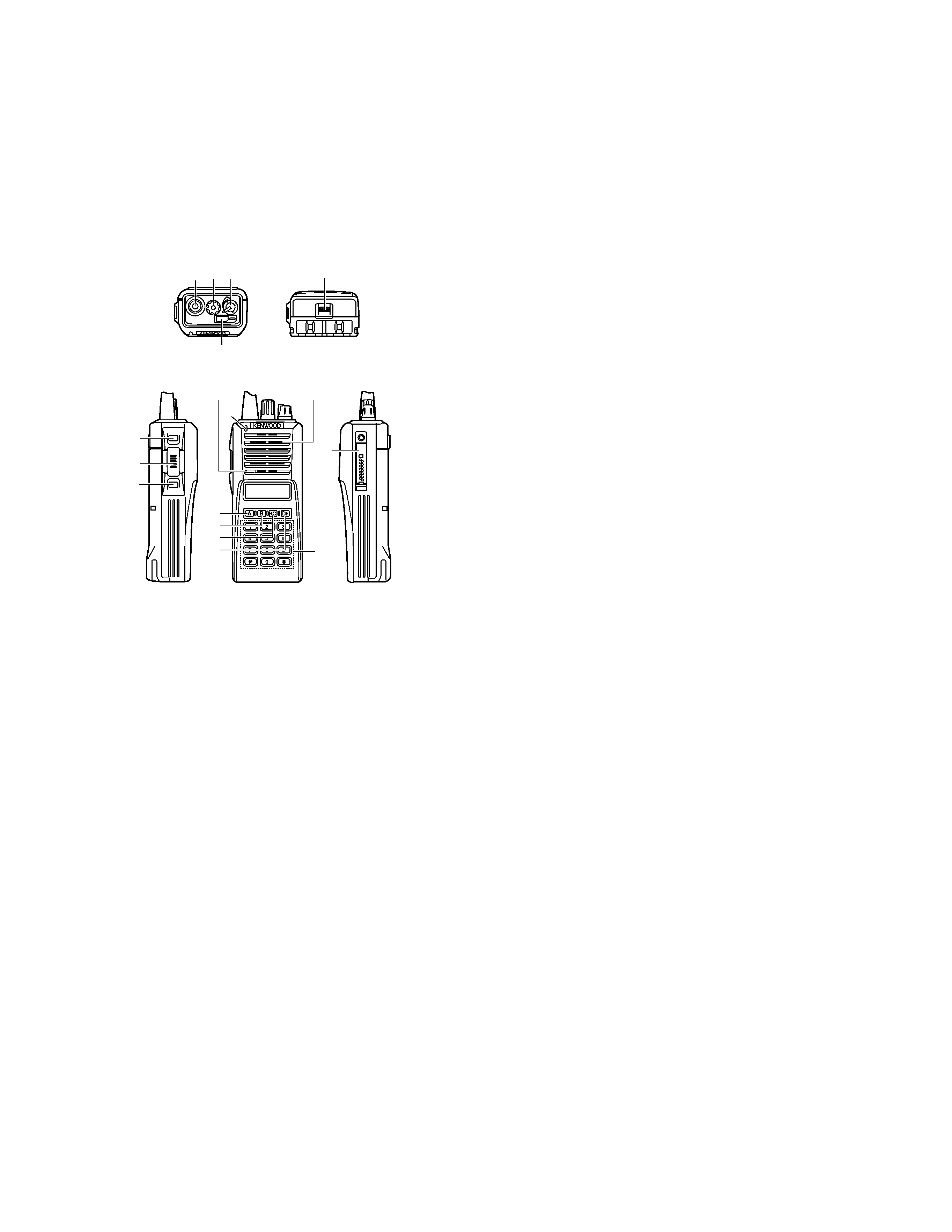
6-4. Function
1. If you press the [Call] switch (top of left side) while "PROG
57600" is displayed, the version is displayed. If you press
the [Call] switch again while the version is displayed, "PROG
57600" is redisplayed.
2. If you press the [Clear] switch (bottom of left side) while
"PROG 57600" is displayed, the display changes to "PROG
19200" to indicate that the write speed is low speed (19200
bps). If you press the [Clear] switch again while "PROG
19200" is displayed, the display changes to "PROG 38400",
and the write speed becomes the middle-speed mode
(38400 bps). If you press the [Clear] switch again while
"PROG 38400" is displayed, the display returns to "PROG
57600".
3. If you press the [Clear] switch while the version is displayed,
the checksum is displayed. If you press the [Clear] switch
again while the checksum is displayed, the version is
redisplayed.
Note:
Normally, write in the high-speed mode.
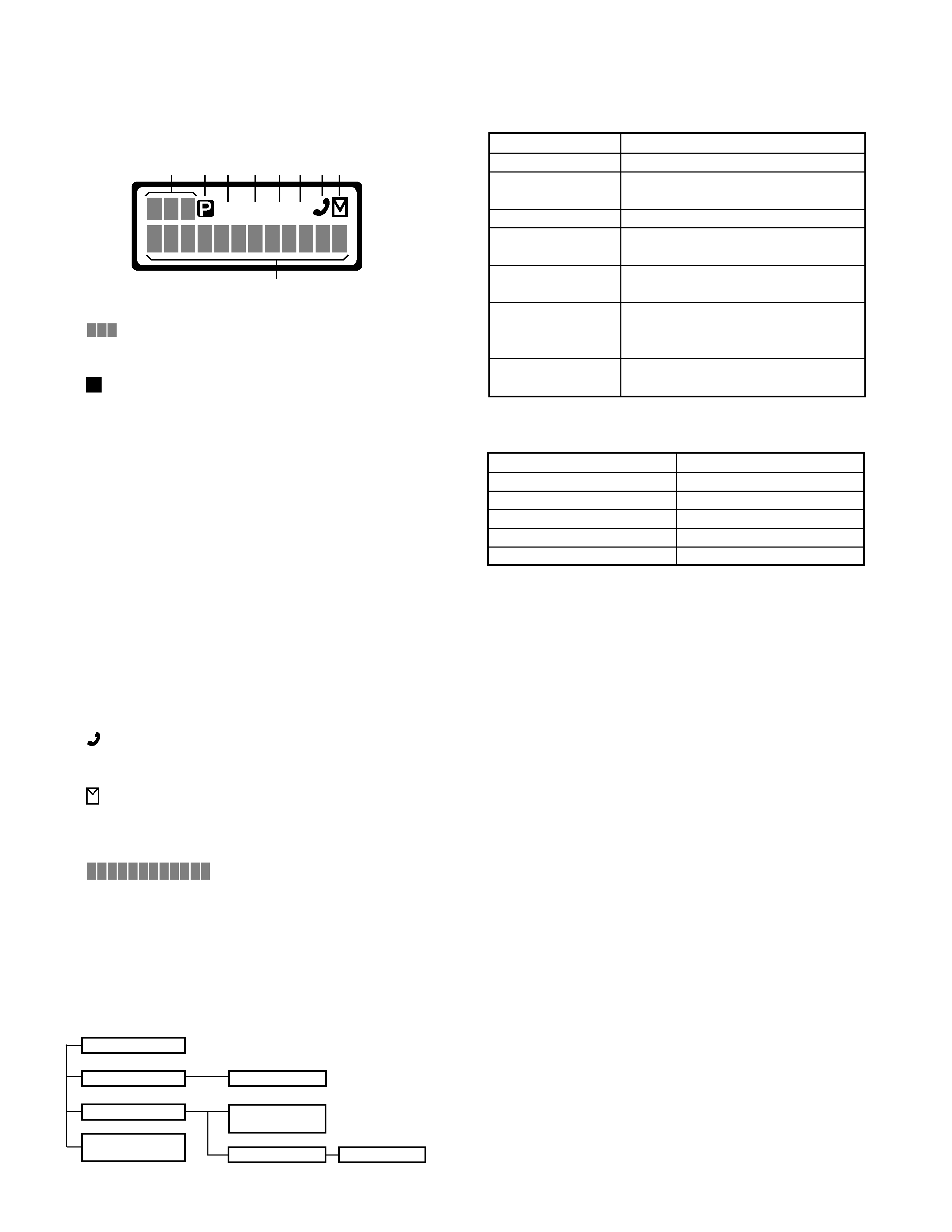
KPG-36
IBM-PC
KPG-62D
Fig. 1
6. Firmware Programming Mode
6-1. Preface
Flash memory is mounted on the TK-285. This allows the
TK-285 to be upgraded when new features are released in the
future. (For details on how to obtain the firmware, contact
Customer Service.)
6-2. Connection procedure
Connect the TK-285 to the personal computer (IBM PC or
compatible) with the interface cable (KPG-36). (Connection is
the same as in the PC Mode.)

Reviews

There are no reviews of this manual yet.