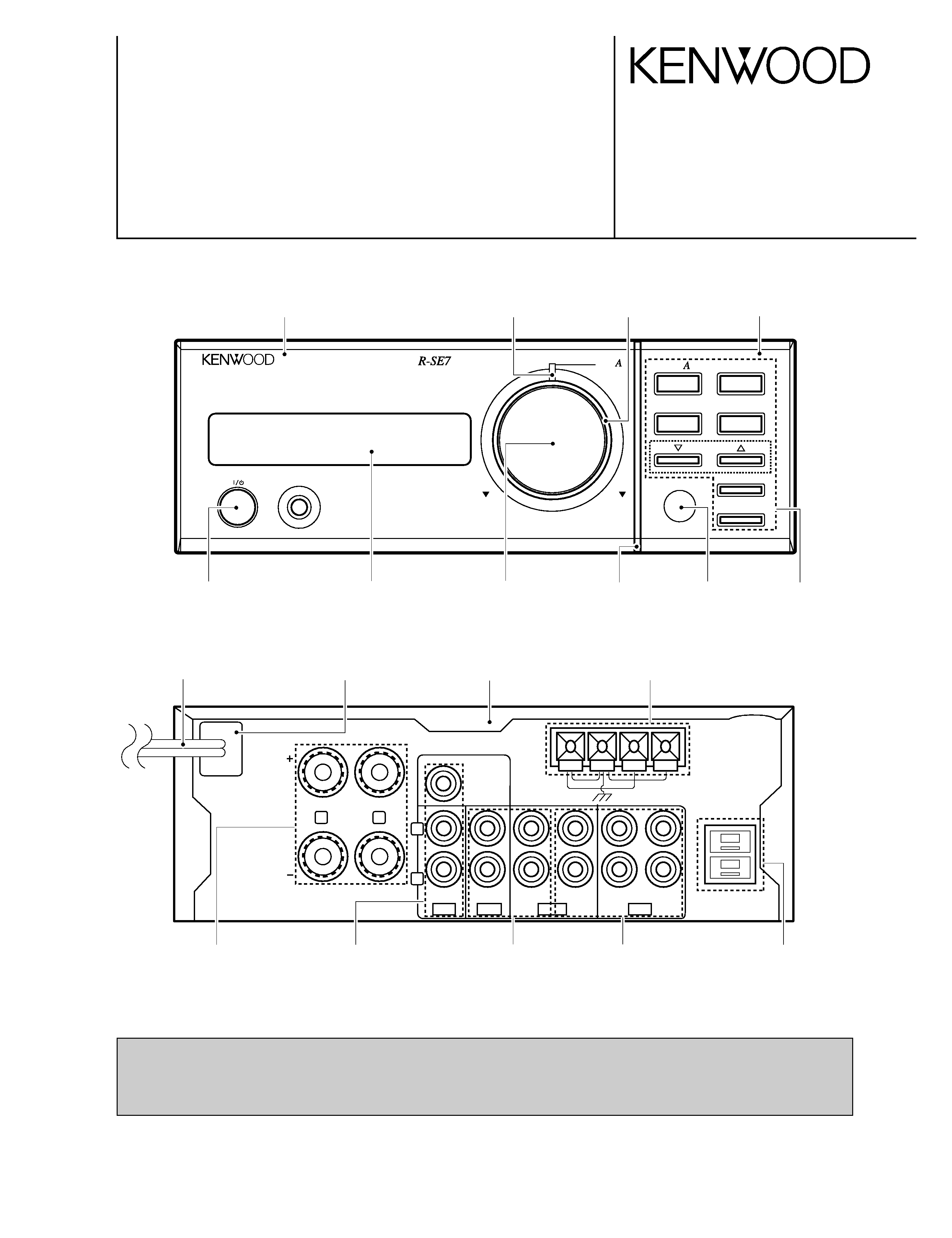
KENWOOD RSE7G Service Manual

Cover page of KENWOOD RSE7G Service Manual

Service Manual for KENWOOD RSE7G, downloadable as a PDF file.

Manual details

  • Immediate download after payment.
  • Delivered as a PDF file.
  • The manual has 27 pages
  • File size: 3.27 MB
  • Available language versions: English
  • Different language versions may vary sligthly in file size and page count.

We guarantee that...

  • our manuals are complete,
  • the manual includes circuit diagrams,
  • our manuals are checked with antivirus,
  • We'll issue refund if the manual is damaged, incomplete or unreadable (our refund policy)

Sample pages

Thumbnail of page 1Thumbnail of page 2Thumbnail of page 3Thumbnail of page 4
Thumbnail of page 5Thumbnail of page 6Thumbnail of page 7Thumbnail of page 8
Thumbnail of page 9
background image
STEREO INTEGRATED AMPLIFIER/TUNER
R-SE7/SE-7(G)
SERVICE MANUAL
©1997-10/B51-5373-00 (K/K) 3191
stereo integrated amplifier/tuner
on/standby
phones
down
up
volume
control
pure
input selector
N.B.
pure
enter
band
auto/mono
turning
SPEAKER
(6 ­ 16
)
R
L
SUB
WOOFER
PRE OUT
FM75
FM300
GND
AM
ANTENA
SYSTEM
CONTROL
R
L
IN
IN
CD
AUX
REC OUT
PLAY OUT
REC OUT
PLAY OUT
TAPE
MD
Panel *
(A60-)
Front glass
(B10-2373-03)
Indicator
(B12-0322-04)
Panel *
(A60-)
AC power cord *
(E30-)
Lock terminal board *
(E70-)
Phono jack
(E63-1014-05)
Phono jack
(E63-0046-15)
Phono jack
(E63-0047-15)
Rectangular receptacle
(E08-0312-05)
Metallic cabinet *
(A01-)
Lock terminal board
(E20-0476-05)
Power cord bushing
(J42-0083-05)
Knob
(K29-6744-04)
Escutcheon
(B07-2363-04)
Indicator
(B12-0320-04)
Knob
(K29-6358-04)
Knob
(K29-6750-03)
Escutcheon
(B07-2367-03)
(HM-701)
PRECAUTIONS FOR REPAIR
· For the SERIAL TEST CODE LIST of the circuit description, see Service manual (B51-5210-00) of R-SA7.
· No connection of ground line if disassemble the unit.
· Please connection the ground line on rear panel, PCBs, Chassis and some others.
* Refer to parts list on page 25.
R-SE7/SE-7(G)(K)COVER(97.11.280:22AM y[W 2
background image
FM indoor antenna (1)
(T90-0182-15) : KM
(T90-0806-05) : ET
DISPLAY
SLEEP
TAPE
REMOTE
CONTROL
UNIT
RC-SE9
1
2
3
RANDOM
4
5
6
CLEAR
7
8
9
P.MODE
O.T.E.
0
+10
EDIT
TUNER BAND
INPUT
N.B.
MUTE
VOLUME CONTROL
MD
CD
P.CALL
Batteries (R6/AA) (2)
AM loop antenna stand (1)
(J19-3645-05)
AM loop antenna (1)
(T90-0820-05)
Audio cords (2)
(E30-0615-05)
System control cord (1)
(E30-2628-05)
Battery cover (A09-0374-08)
Remote control unit (1)
(A70-1154-05) : KM
(A70-1155-05) : TE
R-SE7/SE-7(G)
CONTENTS / ACCESSORIES
2
CONTENTS / ACCESSORIES .................................. 2
CIRCUIT DESCRIPTION ............................................3
ADJUSTMENT ............................................................8
PC BOARD .............................................................. 10
SCHEMATIC DIAGRAM .......................................... 13
EXPLODED VIEW ....................................................24
PARTS LIST..............................................................25
SPECIFICATIONS ......................................Back cover
Contents
Accessories
System configuration
SYSTEM NAME
AMP/TUNER
CD PLAYER
SPEAKER
HM-701
R-SE7
DP-SE7
LS-SE7
R-SE7/SE-7(G)(K)COVER(97.11.280:22AM y[W 3
background image
R-SE7/SE-7(G)
3
CIRCUIT DESCRIPTION
Channel
BAND
E TYPE
Channel
BAND
E TYPE
01ch
FM
87.50MHz
11ch
FM
90.00MHz
02ch
FM
97.50MHz
12ch
FM
98.00MHz
03ch
FM
108.00MHZ
13ch
FM
98.50MHz
04ch
AM
630kHz
14ch
FM
106.00MHz
05ch
AM
990kHz
15ch
AM
531kHz
06ch
AM
1440kHz
16ch
AM
990kHz
07ch
FM
87.50MHz
17ch
AM
1602kHz
08ch
FM
87.50MHz
18ch
FM
87.50MHz
09ch
FM
87.50MHz
19ch
FM
87.50MHz
10ch
FM
89.10MHz
20ch
FM
87.50MHz
1. INITIAL STATE
(1) AMP-related block
E
POWER
OFF
E
SELECTOR SOURCE
TUNER
E
DISPLAY
SELECTOR
E
N.B. CIRCUIT
OFF
E
A CLASS VOLUME VALUE
1.40 STEP
E
AB CLASS VOLUME VALUE 7 STEP
E
PURE MODE
NORMAL (AB CLASS)
E
AUTO POWER SAVE
OFF
E
MULTI CONTROL MODE
INPUT SEL.(R-SE9 only)
(2) TUNER-related block
E
BAND
FM
E
FREQUENCY
Lower-limit value of
receiving frequency.
FM
87.5 MHz
AM
531 kHz
E
AUTO/MANUAL
AUTO
E
P.CH MEMORY
Last frequency
E
Last P.CH
01ch
E
RDS DATA TABLE MEMORY
NO DATA
(3) TIMER-rated block
E
CLOCK
STOP (AM12:00)
E
PROGRAM
WORKING MODE OFF
CONTENTS OF PROGR.
ON=AM 12:00
OFF=AM 12:00
PLAY MODE=PLAY
SELECTOR=TUNER(1ch)
REC MODE OFF
E
O.T.T
WORKING MODE OFF
OTT ON TIME
AM 7:00
(4) TEST PRESET FREQUENCY
2. BACKUP
This function holds the current state of the unit even if the
AC power of the receiver is turned OFF.
(1) Operation outline
The backup state set command signal (CE) of a microcom-
puter is set low when the AC power is turned OFF. The
microcomputer detects the signal and enters the stop state.
The microcomputer is reset when the AC power is turned
ON. The data for backup state confirmation is checked by
reset processing.
The microcomputer is initialized when the data was
destroyed. If it is not destroyed, the microcomputer is started
in the backup state.
E
The data for backup state confirmation is written in a RAM
area.
E
The microcomputer is set to the STOP mode so as to
save the power consumption.
E
A backup state set command signal is detected by a timer
interrupt of 1 msec.
E
The backup guarantee period is set in a circuit.
(2) Backup state setting
E
The data (A596, 5A69H) for backup state confirmation is
written in a RAM area.
(3) Contents of backup data to be held
[[[
AMP [[[
E
POWER ON/OFF
E
DISPLAY MODE
E
SELECTOR SOURCE
E
N.B. CIRCUIT MODE
E
A CLASS VOLUME VALUE
E
AB CLASS VOLUME VALUE
E
PURE A MODE
[[[
TUNER [[[
E
LAST BAND
E
PRESET CHANNEL/RECEIVING STATION FRE-
QUENCY/PI/TA/PTY/PS
E
LAST RECEIVING STATION FREQUENCY AND PRE-
SET CHANNEL (AM/FM)
E
PRESET MEMORY data (1ch~40ch)
E
AUTO/MANUAL
[[[
CLOCK/TIMER [[[
E
LAST CLOCK DATA
E
PROGRAMMED CONTENTS/PROGRAM TIMER WOR-
KING MODE ON/OFF
E
O.T.T. SETTING TIME/O.T.T. WORKING MODE
ON/OFF
The initial setting is performed in a following event :
1. When backup memory data is destroyed when reset is
applied to the microprocessor.
2. When the power cord is plugged in to the AC wall outlet
while pressing the on/standby key.
R-SE7/SE-7(G)(K)COVER(97.11.280:22AM y[W 6
background image
R-SE7/SE-7(G)
4
CIRCUIT DESCRIPTION
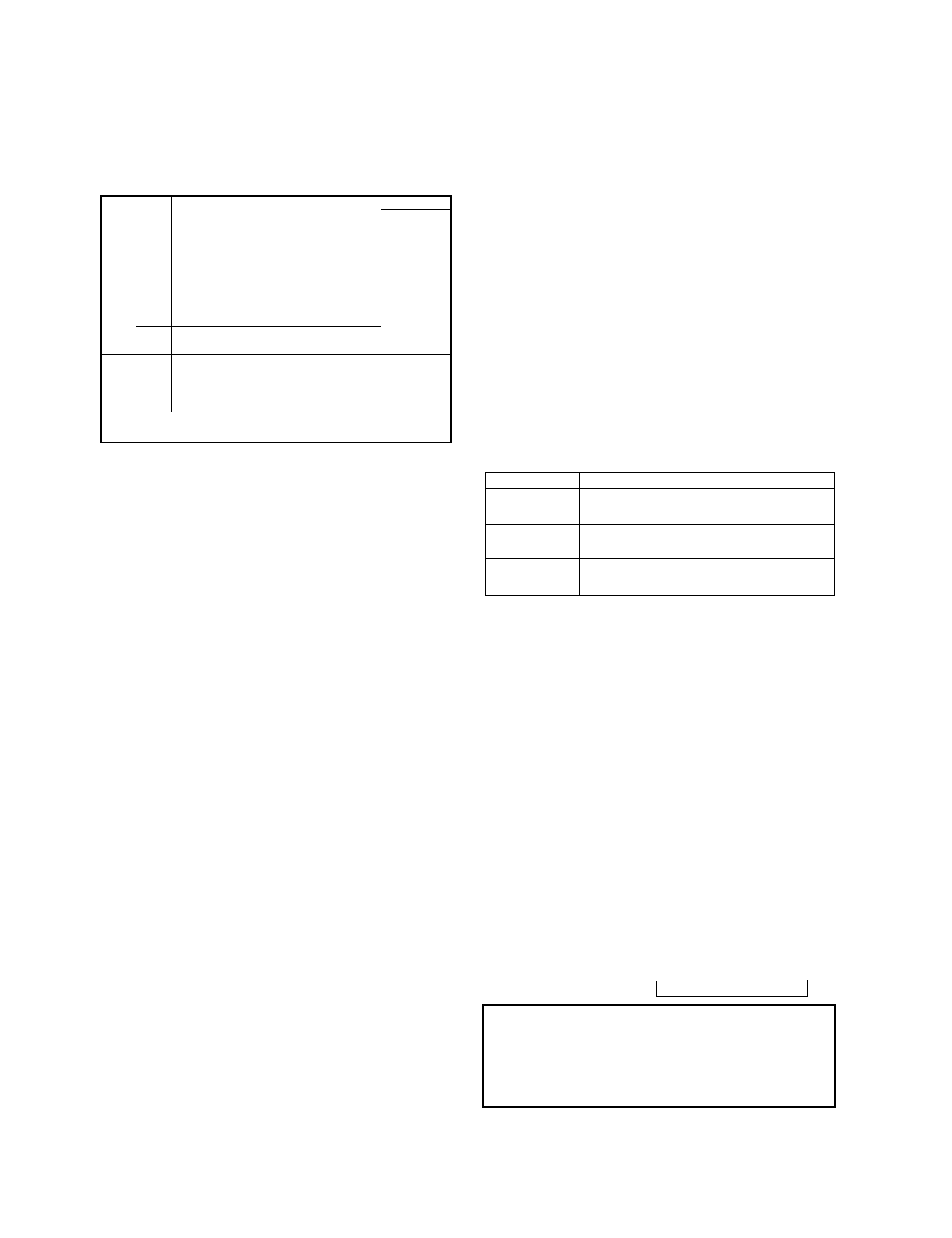
3. DESTINATION LIST OF TUNER
3-1 Destination List of Tuner
4. TEST MODE
4-1. Initializing
The system is initialized when the power is turned on while
pressing the on/standby key.
(1) Contents of operation
E
All the functions are initialized.
4-2. AMP test mode using main unit's keys
4-2-1. Entering the AMP test mode
E
Turn on the power while pressing the BAND key.
4-2-2. Canceling the AMP test mode
E
By turning off the power, the system is initialized and the
test mode is canceled.
4-2-3. Contents of AMP test mode
(1) Automatic on/standby ON
E
The POWER ON state is entered whenever the power is
turned on while pressing the BAND key. All functions are
then initialized and activated in the all-lighting mode.
E
Sub-clock oscillation diagnosis function
The oscillation diagnosis (existence of oscillation and
measurement of period) of a sub-clock is performed
before the test mode is entered. If the diagnosis result is
OK, the system enters the test mode.
If the diagnosis result is NG, the oscillation of the sub-
clock is diagnosed again. If the result is OK, the system
enters the test mode. If the diagnosis result is continu-
ously NG five times, the system stops with ERR 1 and
ERR 2 displayed.
(2) All-lighting mode
E
All the fluorescent display indicators and LED lamps light
when the power is turned on while pressing the BAND
key.
E
After that, the all-lighting mode is canceled when any
main unit's key is pressed. The normal display obtained
when the selector is set to TUNER then appears.
(3) Others
E
The AMP test mode is not terminated even if the selector
is set to positions other than TUNER.
E
In the AMP test mode, the muting during mode selection
is not controlled. However, the operation during the
power-on sequence is the same as the normal operation.
E
The SP protection operation is also the same as the nor-
mal operation.
E
In the AMP test mode using main unit's keys, the keys
below provide a special operation according to the posi-
tion where the selector is set. The main unit's keys
except described below and the rotary encoder provide
the normal operation.
(4) When selector is set to TUNER
Key
Operation
PURE A key
Increments the P.CALL every time this
key is pressed.
N.B. key
Decrement the P.CALL every time this
key is pressed.
ENTER key
Selects the display cyclically in the order
below every time this key is pressed.
@
Write data in the unused area of E2PROM, then read the
written data. If the read data is the same as the written
data, "RAM OK" is displayed in the fluorescent display
indicator. If the former is different from the latter, "RAM
NG" is displayed.
A
Set the TUNER ATT to OFF and display the S level in
hexadecimal when the ENTER key is pressed. ("ATT
OFF **" is displayed in the fluorescent display indicator.)
B
Set the TUNER ATT to ON and display the S level in
hexadecimal when the ENTER key is pressed. ("ATT ON
**" is displayed in the fluorescent display indicator.)
* The special display using the ENTER key is continued until
the next operation is carried out. (**: S LEVEL)
When keys other than ENTER are pressed in items
@
to
B
above, the TUNER ATT is set to OFF and the normal display
appears. The operation corresponding to the key that has
been pressed is performed in this case.
(5) When selector is set to positions other than TUNER
Desti-
Receive
Channel
PLL
DIODE SW
nation
BAND frequency
space
1F
reference DSW1 DSW2
range
frequency D518 D519
FM
87.5MHz~
100kHz +10.7MHz
25kHz
K1
108.0MHz
AM
530kHz~
10kHz
+450kHz
10kHz
1
1
1700kHz
FM
87.5MHz~
50kHz
+10.7MHz
25kHz
E1
108.0MHz
AM
531kHz~
9kHz
+450kHz
9kHz
0
1
1602kHz
FM
87.5MHz~
50kHz
+10.7MHz
25kHz
E3
108.0MHz
(RDS)
AM
531kHz~
9kHz
+450kHz
9kHz
1
0
1602kHz
M
K2 or E1 is changed the setting "DSW1".
X
1
(DSW1=1 : K2, 0 = E1)
0 : NO DIODE
1 : DIODE
X : SWITCHING TRANSISTOR
[ENTER key] Every time this key is pressed, master VOL-
UME level is selected cyclically.
INITIALIZE level ìî MAX î MID î MIN ì
Value of Master
VOLUME
Press the ENTER key.
Press the PURE A key,
then press the ENTER key.
MAX
86
16.00
MID
40
8.00
MIN
1
0.20
INITIALIZE
7
1.40
R-SE7/SE-7(G)(K)COVER(97.11.280:22AM y[W 7
background image
R-SE7/SE-7(G)
5
CIRCUIT DESCRIPTION
[ AUTO key ] Selects the MUTE operation and equalizer
cyclically in the order below for operation display every time
this key is pressed.
-- -> MUTE operation -> Minimum -> Maximum -> Pre-condition --
In the operation for except the AUTO key, become pre-
condition equlizer .
Pre condition : The equlizer becomes the condition to be
pushed the AUTO key before
(include N.B. circuit).
(6) SERIAL TEST CODE LIST
Refer to Service manual (B51-5210-00) of R-SA7 on
page 7.
[ BAND key ] Every time this key is pressed, all the displays
go off and the normal display is selected cyclically.
4-3. RDS test mode using main unit's keys
4-3-1. Entering the RDS test mode
E
Turn on the power while pressing the TUNING UP key.
4-3-2. Canceling the RDS test mode
E
By turning off the power, the system is initialized and the
test mode is canceled.
4-3-3. Contents of RDS test mode
E
The POWER ON state is entered whenever the power is
turned on while pressing the TUNING UP key. All the
functions are then initialized.
E
In the RDS test mode using main unit's keys, the keys
below provides a special operation according to the posi-
tion where the selector is set. The main unit's keys
except described below and the rotary encoder provide
the normal operation.
Key
Operation
CLASS A key
Performs the same operation as for
remote control key "DISPLAY" every time
this key is pressed.
INPUT SEL. key
Performs the same operation as for
remote control key "PTY" every time this
key is pressed.
N.B. key
Performs the same operation as for
remote control key "TA" every time this
key is pressed.
ENTER key
Selects the display cyclically in the order
below every time this key is pressed.
@
Write data in the unused area of EEPROM, then read the
written data. If the read data is the same as the written
data, "RAM OK" is displayed in the fluorescent display
indicator. If the former is different from the latter, "RAM
NG" is displayed.
A
Set the TUNER ATT to OFF and display the S level in
hexadecimal when the ENTER key is pressed. ("ATT
OFF **" is displayed in the fluorescent display indicator.)
B
Set the TUNER ATT to ON and display the S level in
hexadecimal when the ENTER key is pressed. ("ATT ON
**" is displayed in the fluorescent display indicator.)
* The special display using the ENTER key is continued until
the next operation is carried out. (**: S LEVEL)
When keys other than ENTER are pressed in items
@
to
B
above, the TUNER ATT is set to OFF and the normal display
appears. The operation corresponding to the key that has
been pressed is performed in this case.
4-4. SERIAL TEST MODE
(1) Setting the serial test mode
The unit is put into the serial test mode when a serial code
"TEST ON" is input during the POWER-ON sequence.
In the 16-bit serial test mode, serial code C27FH is input.
E
In the serial test mode, all remote control keys and ordi-
nary serial codes are disabled. Only the panel keys per-
form the same operation as usually.
(2) Canceling the serial test mode
E
The serial test mode is canceled to return to the ordinary
mode by inputting a "TEST OFF" code (C27 EH). After
the ordinary mode was returned, the serial mode is
returned to the state before the test mode is entered.
The backup operation is not initialized.
E
The serial test mode is also canceled when the AC power
is turned OFF.
(3) Cautions
E
The serial test code is prescribed as a 16-bit code only.
E
The operations below are inhibited in the serial test mode.
The operations mentioned above cannot be guaranteed
when they are performed in the serial test mode.
E
An identical code is output when the serial test mode
code is input.
R-SE7/SE-7(G)(K)COVER(97.11.280:22AM y[W 10

Reviews

There are no reviews of this manual yet.