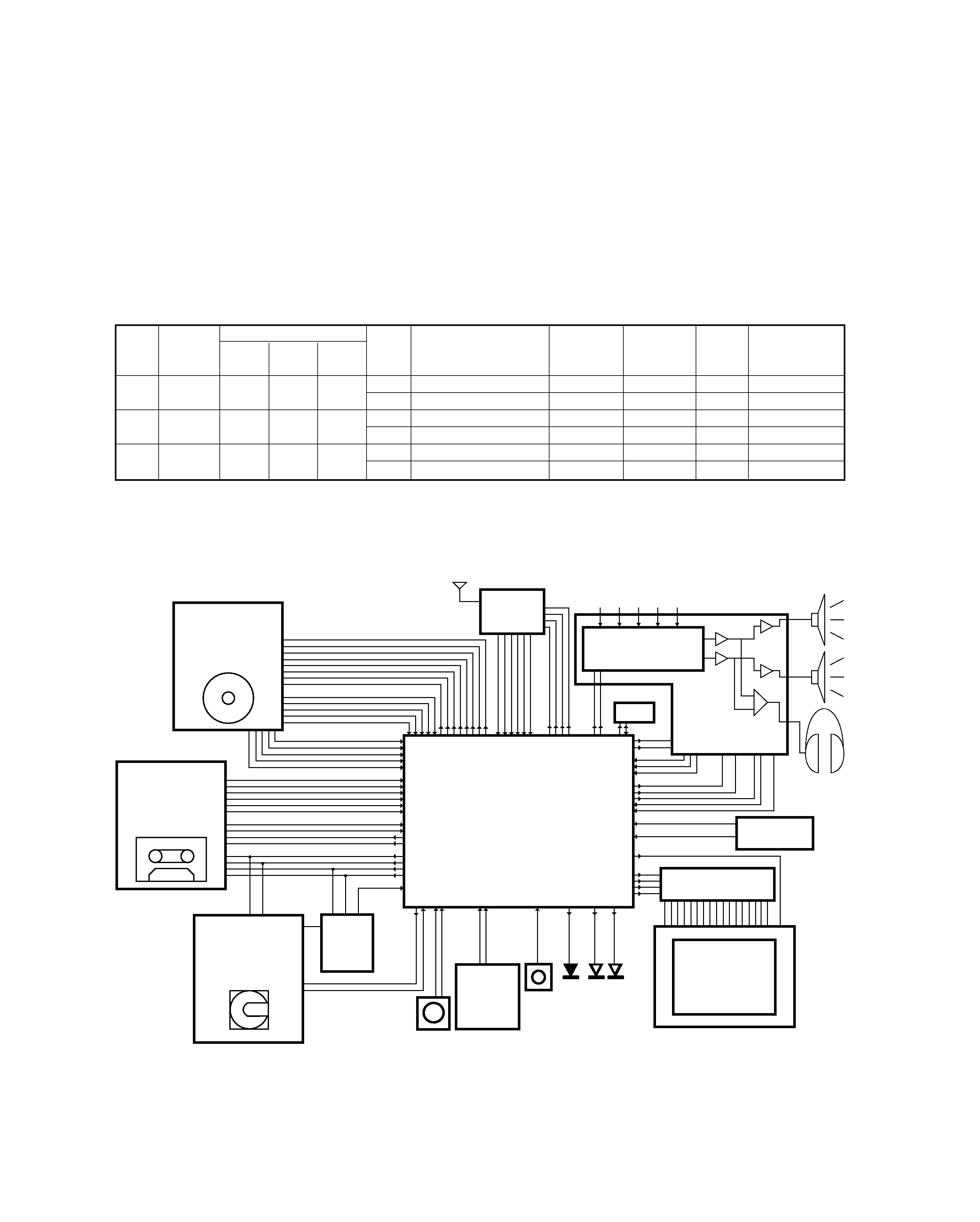
KENWOOD RD-M72MD Service Manual

Cover page of KENWOOD RD-M72MD Service Manual

Service Manual for KENWOOD RD-M72MD, downloadable as a PDF file.

Manual details

  • Immediate download after payment.
  • Delivered as a PDF file.
  • The manual has 37 pages
  • File size: 5.07 MB
  • Available language versions: English
  • Different language versions may vary sligthly in file size and page count.

We guarantee that...

  • our manuals are complete,
  • the manual includes circuit diagrams,
  • our manuals are checked with antivirus,
  • We'll issue refund if the manual is damaged, incomplete or unreadable (our refund policy)

Sample pages

Thumbnail of page 1Thumbnail of page 2Thumbnail of page 3Thumbnail of page 4
Thumbnail of page 5Thumbnail of page 6Thumbnail of page 7Thumbnail of page 8
Thumbnail of page 9
background image
70%
MICRO HiFi COMPONENT SYSTEM
RD-M52MD/M72MD
SERVICE MANUAL
(HM-582MD/682MD/782MD)
© 2000-6/B51-5625-00 (K/K) 2320
&
STO
P
re
c
ph
o
nes
A
U
X
sou
nd
s
et
m
en
u
/
demo
d
is
play
CD
^
M
D
^
>
$
TUN
ER
/BAN
D
r emo
te
disc loading mechanism
micro hi-fi component system
timer
PUSH
volume/
multi-control
Door assy
(A52-0392-02)
Panel
(A29-1095-04)
Knob
(K29-7770-13)
Knob
(K29-7773-04)
Magnet catch
(J52-0043-05)
Front glass
(B10-3585-03)
Indicator
(B12-0394-04)
Dressing panel
(A21-3864-03)
Knob
(K29-7772-14)
Knob
(K29-7769-03)
Magnet catch
(J52-0043-05)
Illustration is RD-M52MD-L.
KENWOOD-Corp. certifies this equipment conforms to DHHS
Regulations No. 21 CFR 1040. 10, Chapter 1, Subchapter J.
DANGER : Laser radiation when open and interlock defeated.
AVOID DIRECT EXPOSURE TO BEAM.
In compliance with Federal Regulations, following are repro-
ductions of labels on, or inside the product relating to laser
product safety.
background image
Operation to reset
The microcomputer may fall into malfunction (impossibil-
ity to operate, erroneous display, etc.) when the power cord
is unplugged while unit is ON or due to an external factor.
In this case, execute the following procedure to reset the
microcomputer and return it to normal condition.
Unplug the power cord from the power outlet then,
while holding the menu/demo key depressed, plug the
power cord again.
÷ Please note that resetting the microcomputer clears the
contents stored in and it returns to condition when it left the
factory.
menu
/demo
RD-M52MD/M72MD
2
CONTENTS / ACCESSORIES / CAUTIONS
CONTENTS / ACCESSORIES / CAUTIONS ............. 2
EXTERNAL VIEW .......................................................3
CIRCUIT DESCRIPTION ............................................4
ADJUSTMENT ..........................................................10
PARTS DESCRIPTIONS ..........................................11
PC BOARD .............................................................. 12
SCHEMATIC DIAGRAM .......................................... 17
EXPLODED VIEW ....................................................31
PARTS LIST..............................................................35
SPECIFICATIONS ....................................................45
Contents
AM loop antenna (1)
(T90-0852-05)
Remote control unit (1)
Battery cover(A09-1161-08)
Batteries (R6/AA) (2)
Speaker cord (2)
FM indoor antenna (1)
(T90-0858-05)
Pin spikes (12)
(D21-1974-04)
Anti-slip sheets (12)
(G16-0878-14)
RD-M72MD ONLY
Cleaning cloth (1)
(W01-0990-04)
Feet for speaker (8)
Accessories
Cautions
REMOTE CONTROLLER
MODEL NAME
MODEL
DESTINATIONS
BATTERY COVER
A70-1385-05
RC-M0507E-IT
RD-M72MD
THE
A09-1183-08
A70-1399-05
RC-M0301E
RXD-M52MD-S
T2
A09-1161-08
A70-1399-05
RC-M0301E
RXD-M52MD-L
THE
A09-1161-08
SYSTEM
MAIN UNIT
DESTINATION
SPEAKER
SP CORD PARTS No
FOOT FOR SPEAKER
HM-582MD-L
RD-M52MD-L
ETH
LS-M52-L
E30-5828-05
J02-0624-08
HM-682MD
RD-M52MD-S
T2
LS-M52-S
E30-5828-05
J02-0624-08
HM-782MD
RD-M72MD
ETH
LS-M72
E30-5880-05
J02-0626-08
System configration
Remocon configration
background image
RD-M52MD/M72MD
3
EXTERNAL VIEW
SERIAL NO.
+
-
+
-
R
L
SUB
WOOFER
PRE OUT
DIGITAL IN
OPTICAL
OU T
I N
AUX
(TAPE/MD)
ANTENNA
FM
75
GND
AM
SPEAKERS
( 6-16
)
R
L
Optical receiving module
(W02-2731-05)
AC power cord *
(E30-)
AC power cord bushing
(J42-0083-05)
Lock terminal board
(E70-0127-05)
Pin jack
(E63-1082-05)
Lock terminal board
(E70-0053-05)
Pin jack
(E63-0164-05)
background image
CD mecha unit
CDM-34
DECK mecha unit
NJU3713D (IC4)
EXPANDER IC
X28
MDM-06
MD mecha unit
HD6432227N01FA
Back up
circuit
A/D
X29, IC1
M30624MG-304FP(DECK)
-303FP(MD)
SIO
SIO
PWM
Main uCOM
PWM
A/D
A/D
AMP hadrware
circuit
AMP_ system_IC
(input selecter)
TUNER unit
(RDS unit)
CD TAPE MD TUNER AUX
X29, IC8
A/D
A/D
A/D
INT
INT
RESET
EEPROM
INT
INT
UART
A/D A/D
encoder
REM
stnby
eject
cd md/ tape
Key matrix
(8keys X
2 lines)
LCD module
(6464dot)
LCD driver
RESET & CE
circuit
(mech ucom)
RD-M52MD/M72MD
4
CIRCUIT DESCRIPTION
3. Microprocessor :M30624MG-303FP(MD version)
:M30624MG-304FP(DECK version)
3-1 Microprocessor periphery block diagram
DESTI-
DESTINATION SW
RECEIVING
CHANNEL
UNIT
3
2
1
BAND
FREQUNY
IF
RF
EMPHASIS
NATION
(40Pin) (39Pin) (38Pin)
RANGE
SPACE
K,P
KI
0
0
0
FM
87.5MHz~108.0MHz
100kHz
+10.7MHz
25kHz
1
AM
530kHz~ 1700kHz
10kHz
+450kHz
10kHz
0
ME1
0
0
1
FM
87.5MHz~108.0MHz
50kHz
+10.7MHz
25kHz
0
AM
531kHz~ 1602kHz
9kHz
+450kHz
9kHz
0
E,T
E3
11
0
FM
87.5MHz~108.0MHz
50kHz
+10.7MHz
25kHz
0
(RDS)
AM
531kHz~ 1602kHz
9kHz
+450kHz
9kHz
0
1.Initializing the CD/MD Receiver
1-1Initialization Method
The CD/MD receiver will be initialized when you pressed [SOUND] key and turn the AC on.
1-2 Contents of Initialization
1 MD disc wil not be ejected from MD mechanism.
2 CD disc will be ejected from CD mechanism.
2.Conditions according to the Destination
( ) Port of Microprocessor
background image
RD-M52MD/M72MD
5
CIRCUIT DESCRIPTION
3-2 Pin Description of Microprocessor
Pin No.
Pin Name
I/O
Description
1
8SW2
I
Detection port of 8cm disc for CD mechanism.
2
SCLK
O
Clock output to DSP IC(X29,IC9).
3
SENS
I
Sense input port from DSP IC(X29,IC9).
4
FAN/DA
O
Control port of fan motor.
5
DATA
O
Data output to DSP IC(X29,IC9).
6
XRST
O
Reset output to DSP IC(X29,IC9).
7
CLOK
O
Clock output to DSP IC(X29,IC9).
8
BYTE
-
Connected to ground.
9
CNVSS
-
Connected to ground.
10
XTIN
I
Clock input(32.768kHz).
11
XTOUT
O
Clock output(32.768kHz).
12
RESET
I
Reset signal input.
13
XOUT
O
Main clock output(1MHz).
14
VSS
-
Connected to ground.
15
XIN
I
Main clock input(1MHz).
16
VCC
-
Power supply.
17
NMI
-
Power supply.
18
u-COM CE
I
Detection port of AC off.
19
REM
I
Input port of remote control signal.
20
SCOR
I
Input port of sub code synchronized signal.
21
STBY RED
O
Standby LED(red) control terminal.
22
LCD BKLT
O
Control terminal of LCD back light.
23
STBY GR
O
Standby LED(green) control terminal.
24
LED CD
O
LED(CD) control terminal.
25
LED MD/TAPE
O
LED(MD/TAPE) control terminal.
26
CD XLAT
O
Latch output to DSP IC(X29,IC9).
27
ENC A
I
Input port of volume encoder.
28
ENC B
I
Input port of volume encoder.
29
MD RXD
I
Data input from MD mechanism microprocessor.
30
MD TXD
O
Transmission data output to MD mechanism microprocessor.
31
LCD SI
O
Data output to LCD driver.
32
LCD AO
O
AO control to LCD driver.
33
LCD SCL
O
Clock output to LCD driver.
34
LCD RST
O
Reset output to LCD driver.
35
SMK M/D
I
Discrimination port for deck and MD.
36
SQSO
I
Data input for CD sub Q data.
37
SQCK
O
Clock output for CD sub Q data.
38-40
SMK1-3
I
Discrimination port of destination for TUNER.
41
STB
O
Strobe output to NJU3713D(X28,IC4).
42
W/R
O
Unused.
43
SDA
I/O
E2PROM data.
44
SCL
O
E2PROM clock output.
45
OP SW
I
Input port of open switch for deck(deck version only).
46
LCD CSI
O
CE output to LCD driver.
47
CL SW
I
Input port of close switch for deck(deck version only).
48
PH SW
I
Input port of photo sensor for deck(deck version only).
49
REC F SW
I
Deck forward switch input(deck version only).
50
HALF SW
I
Input port of half switch for deck(deck version only).
51
PLAY SW
I
Input port of play switch for deck(deck version only).
52
TYPE SW
I
Detection port for tape type(Normal/CrO2).
53
REC R SW
I
Deck reverse switch input(deck version only).
54
SBUSY
-
Unused.
55
SDATA
-
Unused.
56
RDS DATA
I
RDS data input(E/T type only).
57
TMUTE
O
TUNER muting control.
58
SD
I
Detection terminal of SD signal for TUNER.
59
ST
I
Detection terminal of stereo signal for TUNER.
60
PLL DATA
O
Data output to PLL IC.
61
PLL CLK
O
Clock output to PLL IC.
62
VCC
-
Power supply.

Reviews

There are no reviews of this manual yet.