KENWOOD NXR-901 Owner's Manual

Cover page of KENWOOD NXR-901 Owner's Manual

Owner's Manual for KENWOOD NXR-901, downloadable as a PDF file.

Manual details

  • Immediate download after payment.
  • Delivered as a PDF file.
  • The manual has 8 pages
  • File size: 0.17 MB
  • Available language versions: French, English, Spanish
  • Different language versions may vary sligthly in file size and page count.

We guarantee that...

  • our manuals are complete,
  • our manuals are checked with antivirus,
  • We'll issue refund if the manual is damaged, incomplete or unreadable (our refund policy)

Sample pages

Thumbnail of page 1Thumbnail of page 2Thumbnail of page 3Thumbnail of page 4
Thumbnail of page 5Thumbnail of page 6Thumbnail of page 7Thumbnail of page 8
Thumbnail of page 9
background image
NXR-900/ NXR-901
INSTRUCTION MANUAL
© B62-2410-00 (K)
09 08 07 06 05 04 03 02 01 00
MANUAL DE INSTRUCCTIONES
MODE D'EMPLOI
BASE-REPETIDOR DIGITAL 800MHz/ BASE-REPETIDOR DIGITAL 900MHz
800MHz DIGITAL BASE-REPEATER/ 900MHz DIGITAL BASE-REPEATER
BASE-RELAIS NUMÉRIQUE 800MHz/ BASE-RELAIS NUMÉRIQUE 900MHz
background image
B
This repeater is intended for use as a fixed base station with
the antenna located outdoors on the rooftop or on an antenna
tower. (except USA and Canada)
This repeater is designed for a 13.8 V DC power source!
Never use a 24 V DC or higher source to power the repeater.
Use only the supplied DC cord.
Do not remove the ferrite core attached to the DC cord. Doing
so may cause interference with radio communications.
UNPACKING AND CHECKING EQUIPMENT
Note:
The following unpacking information is for use by your
Kenwood dealer, an authorized Kenwood service center, or the
factory.
Carefully unpack the repeater. We recommend that you identify
the items listed in the following table before discarding the
packing material. If any items are missing or have been damaged
during shipment, file a claim with the carrier immediately.
Item
Part Number
Quantity
Front glass
B10-2781-XX
1
Dressed screw
N08-0563-XX
1
Bracket
J29-0725-XX
2
Flat head machine screw
N32-4008-XX
4
Handle and screw set
K01-0421-XX
1
DC cord
E30-3344-XX
1
Lead wire with connector (15 pin)
E37-1381-XX
1
Fuse (7.5 A)
F05-7521-XX
1
SYNC Cable
E30-7701-XX
1
Instruction Manual
B62-2410-XX
1
INSTALLATION
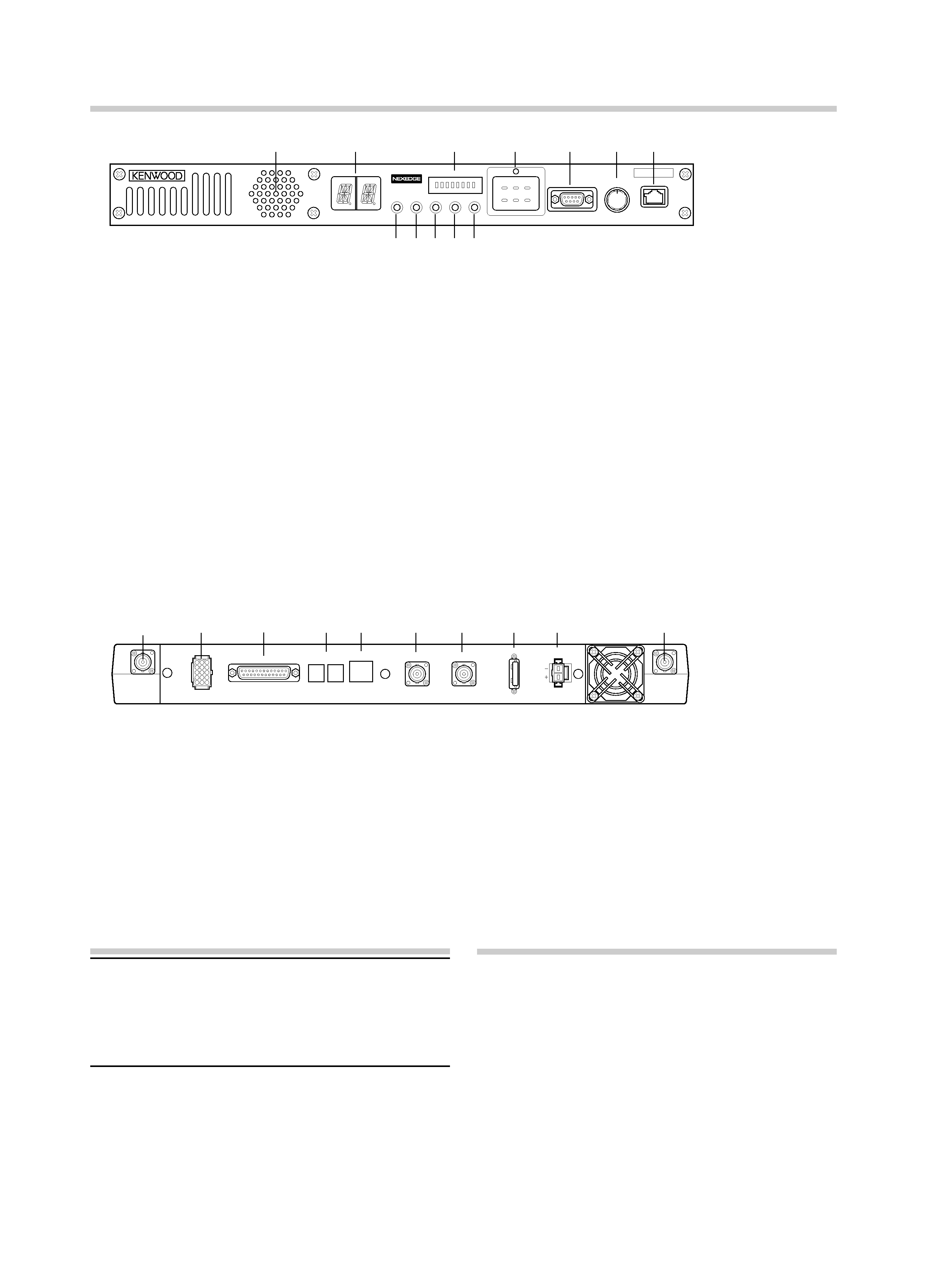
To install the handles onto the front panel of the repeater, align
the handles with the holes on the front panel, then secure the
handles using the supplied screws.
Please consult your dealer for installing the repeater and
antenna.
MICROPHONE
Connect an optional KMC-30, KMC-35, or KMC-9C Kenwood
microphone to the MICROPHONE jack on the front panel.
OCXO UNIT (KXK-3):Option
The OCXO unit (KXK-3) is an Oven Controlled Crystal Oscillator
(OCXO) unit.
NOTICES TO THE USER
Government law prohibits the operation of unlicensed radio
transmitters within the territories under government control.
Illegal operation is punishable by fine and/or imprisonment.
Refer service to qualified technicians only.
FCC WARNING
This equipment generates or uses radio frequency energy. Changes
or modifications to this equipment may cause harmful interference
unless the modifications are expressly approved in the instruction
manual. The user could lose the authority to operate this equipment if
an unauthorized change or modification is made.
INFORMATION TO THE DIGITAL DEVICE USER REQUIRED BY
THE FCC
This equipment has been tested and found to comply with the limits
for a Class B digital device, pursuant to Part 15 of the FCC Rules.
These limits are designed to provide reasonable protection against
harmful interference in a residential installation.
This equipment generates, uses and can generate radio frequency
energy and, if not installed and used in accordance with the
instructions, may cause harmful interference to radio communications.
However, there is no guarantee that the interference will not occur
in a particular installation. If this equipment does cause harmful
interference to radio or television reception, which can be determined
by turning the equipment off and on, the user is encouraged to try to
correct the interference by one or more of the following measures:
· Reorient or relocate the receiving antenna.
· Increase the separation between the equipment and receiver.
· Connect the equipment to an outlet on a circuit different from that to
which the receiver is connected.
· Consult the dealer for technical assistance.
THANK YOU!
We are grateful you purchased this Kenwood repeater. We
believe this easy-to-program repeater will be highly effective in
your communications system, and will keep personnel operating
at peak efficiency.
Kenwood incorporates the latest in advanced technology into
all of our products. As a result, we feel strongly that you will be
pleased with the quality and features of this product.
PRECAUTIONS
·
Do not expose the unit to rain or moisture; to prevent fire or
electric shock.
·
Do not open the unit under any circumstances; to avoid risk
of electric shock.
·
Do not expose the unit to long periods of direct sunlight, nor
place it close to heating appliances.
·
Do not place the unit in excessively dusty and/or humid
areas, nor on unstable surfaces.
·
If you detect an abnormal odor or smoke coming from the
unit, disconnect the power from the unit immediately. Contact
your Kenwood service center or dealer.
NXR-900/ NXR-901 INSTRUCTION MANUAL
800MHz DIGITAL BASE-REPEATER/ 900MHz DIGITAL BASE-REPEATER
background image
C
REPEATER OPERATION
Note: Please consult your dealer for programming the repeater.
Due to the frequency stability on the 6.25 kHz bandwidth channel,
when operating the repeater using an optional OCXO unit, allow
the unit to warm up after turning the power on. Refer to the KXK-3
instruction manual concerning the warm up duration.
After turning on the power, wait for approximately 10 seconds for
the VCXO or 5 minutes for the OCXO (when mounting) to warm up.
During this time, the CH/STATUS Display will blink. The keys will
function when they are pressed.
When power is applied to the unit, the POWER indicator lights
green. Turn the VOLUME control clockwise until a click sounds,
to unmute the audio. Rotate to adjust the audio. Turn the
VOLUME control counterclockwise fully to mute the audio.
The BUSY indicator lights green while receiving a signal and the
TX indicator lights red while transmitting.
Rear Panel
q RX IN jack
Connect an RX antenna or a duplexer to this BNC
receptacle.
w TEST/SPKR jack
Test input/output jack. Connect an external speaker to
this jack.
e CONTROL I/O jack
Connect a repeater controller or a remote panel to this
DB-25 interface.
r SYNC 1 / 2 jack
Connect to another repeater to use synchronous frame
signaling for digital trunking.
t LAN jack
Connect to Ethernet.
CONTROLS AND FUNCTIONS
Front Panel
q
wr
t
yu
i
o
e
q
w
rt
y
u
e
MICROPHONE
VOLUME
COM
OFF/
POWER
CTRL
OCXO
BUSY
TX
12
MON TAKE
OVER
RPT
DISABLE
ABC
345678
STATUS
TEST/SPKR
RX
TX
CONTROL I/O
SYNC
12
LAN
REF OUT
REF IN
FUSE
75
DC 13.8V
y REF OUT jack
Connect to another repeater within the site to supply a
reference signal.
u REF IN jack
Connect from another repeater within the site to receive a
reference signal.
i FUSE
Insert 7.5 A blade fuse into this fuse holder.
o DC 13.8V jack
Connect a 13.8 V DC power supply to this jack.
!0 TX OUT jack
Connect a TX antenna or a duplexer to this BNC receptacle.
i
o
!0
TRANSCEIVER OPERATION
Receive
Adjust the volume to your desired level. You may need to
readjust the volume if you are having interference while receiving
a message from your dispatcher or another member in your fleet.
The BUSY indicator lights green while a signal is being received.
Transmit
1 Listen to the channel before transmitting, to make sure it
is not being used.
2 Press the microphone PTT switch, then speak in your
normal speaking voice.
The TX indicator lights red while transmitting.
3 When you finish speaking, release the PTT switch.
!0
!1
!2
q Speaker
w CH/STATUS Display
Two 17-segment digits display the channel number, name,
or status.
e STATUS indicator
Indicates the status of the repeater. (NXDN mode)
r Programmable Function keys
Press these keys to activate their programmable
functions.
t COM jack
Connect to the PC using a RS-232C standard DB9
(Female) cross cable.
y VOLUME control
Turn clockwise until a click sounds, to unmute the audio.
Rotate to adjust the audio. Turn counterclockwise fully to
mute the audio.
u MICROPHONE jack
Connect a microphone to this 8-pin modular jack.
i POWER indicator
Lights green when power is supplied to the DC 13.8V
jack. Blinks red when an abnormal voltage is present.
While blinking, the repeater cannot be used.
o TX indicator
Lights red while transmitting.
!0 BUSY indicator
Lights green while a signal is being received.
!1 OCXO indicator
The OCXO indicator shows the state of the reference
10 MHz oscillator :
Lights Green when using a reference signal from an
optional OCXO unit (KXK-3).
Lights Orange when using a reference signal from another
repeater.
Lights red when no reference signal is available or when
an error occurs.
Does not light when the reference signal is an internal
VCXO signal.
!2 CTRL indicator
The CTRL indicator shows the control channel status
while using Digital trunking :
Lights Green when the repeater is used as control channel.
Blinks Green when using a non-dedicated control channel.
background image
F-1
MODE D'EMPLOI DU NXR-900/ NXR-901
BASE-RELAIS NUMÉRIQUE 800MHz/ BASE-RELAIS NUMÉRIQUE 900MHz
MERCI !
Nous sommes très heureux que vous ayez acheté ce répéteur Kenwood.
Nous pensons que ce répéteur facile à programmer sera extrêmement
efficace dans votre système de communications et restera optimal pour
un fonctionnement personnel.
Kenwood intègre la dernière technologie avancée dans tous nos
produits. Par conséquent, nous avons la nette impression que vous
serez satisfait de la qualité et des caractéristiques de ce produit.
PRECAUTIONS
·
N'exposez pas l'unité à la pluie ou l'humidité pour éviter tout risque
d'incendie ou de choc électrique.
·
N'ouvrez l'unité sous aucun prétexte afin d'éviter tout risque de choc
électrique.
·
N'exposez pas l'unité aux rayons directs du soleil pendant des
périodes prolongées, ne le posez pas non plus à proximité
d'appareils de chauffage.
·
Ne posez pas l'unité dans des endroits extrêmement poussiéreux
et/ou humides, ni sur des surfaces instables.
·
Si vous détectez une odeur anormale ou une fumée provenant de
l'unité, débranchez l'unité immédiatement. Contactez votre centre de
service ou revendeur Kenwood.
REMARQUES DESTINEES A L'UTILISATEUR
La loi gouvernementale interdit l'utilisation d'émetteurs-récepteurs radio
non autorisés sur les territoires sous contrôle gouvernemental.
Une utilisation illégale est punissable d'une amende et/ou d'une peine
d'emprisonnement.
Confiez l'entretien uniquement à des techniciens qualifiés.
ATTENTION
Ce répéteur est conçu pour une utilisation en tant que station de base
fixe avec l'antenne située à l'extérieur sur le toit ou un pylône d'antenne
(sauf États-Unis et Canada).
Ce répéteur est conçu pour une source d'alimentation de 13,8 Vcc !
N'utilisez jamais une source d'alimentation de 24 Vcc ou supérieure
pour alimenter le répéteur.
Utilisez uniquement le câble CC fourni.
N'enlevez pas le noyau magnétique fixé au câble CC. Dans le cas
contraire, cela peut entraîner des interférences avec les communications
radio.
DEBALLAGE ET VERIFICATION DE
L'EQUIPEMENT
Remarque :
Les informations suivantes relatives au déballage doivent être
utilisées par votre revendeur Kenwood, un centre de service agréé Kenwood
ou l'usine.
Déballez le répéteur avec soin. Nous vous recommandons d'identifier
les articles énumérés dans le tableau suivant avant de jeter l'emballage.
Si un article est manquant ou a été endommagé pendant le transport,
remplissez immédiatement un formulaire de plainte avec le transporteur.
Article
Numéro de pièce
Quantité
Glace avant
B10-2781-XX
1
Vis parée
N08-0563-XX
1
Fixation
J29-0725-XX
2
Vis à métaux à tête plate
N32-4008-XX
4
Manche et ensemble de vis
K01-0421-XX
1
Câble CC
E30-3344-XX
1
Fil avec connecteur (15 broches)
E37-1381-XX
1
Fusible (7,5 A)
F05-7521-XX
1
Câble SYNC
E30-7701-XX
1
Mode d'emploi
B62-2410-XX
1
INSTALLATION
Pour installer les poignées sur le panneau avant du répéteur, alignez les
poignées aux orifices sur le panneau avant, ensuite, fixez les poignées à
l'aide des vis fournies.
Veuillez contacter votre revendeur pour l'installation du répéteur et de
l'antenne.
MICROPHONE
Connectez un microphone KMC-30, KMC-35 ou KMC-9C Kenwood en
option à la prise MICROPHONE du panneau avant.
UNITE OCXO (KXK-3) : Option
L'unité OCXO (KXK-3) est un Oscillateur à quartz thermostaté (OCXO).
background image
F-2
FONCTIONNEMENT DU REPETEUR
Remarque :
Veuillez contacter votre revendeur en ce qui concerne la
programmation du répéteur. En raison de la stabilité de fréquence sur le canal
à bande passante 6,25 kHz, lorsque vous utilisez le répéteur à l'aide d'une
unité OCXO en option, laissez l'unité préchauffer après la mise sous tension.
Reportez-vous au Mode d'emploi KXK-3 concernant la durée de préchauffage.
Après la mise sous tension, attendez environ 10 secondes pour le VCXO ou
5 minutes pour le OCXO (lors du montage) pour le préchauffage. Pendant ce
temps, l'afficheur CH/STATUS clignote. Les touches fonctionneront à chaque
pression.
Lorsque l'unité est mise sous tension, l'indicateur vert POWER s'allume.
Tournez la commande VOLUME dans le sens des aiguilles d'une
montre jusqu'à entendre un clic, pour désactiver la sourdine du niveau
sonore. Tournez pour régler le niveau sonore. Tournez complètement la
commande VOLUME dans le sens contraire des aiguilles d'une montre
pour mettre le niveau sonore en sourdine.
L'indicateur vert BUSY s'allume lors de la réception d'un signal et
l'indicateur rouge TX s'allume lors de la transmission.
Panneau arrière
a Prise RX IN
Raccordez une antenne RX ou un duplexeur à ce réceptacle
BNC.
b Prise TEST/SPKR
Testez la prise d'entrée/sortie. Raccordez un haut-parleur
externe à cette prise.
c Prise CONTROL I/O
Raccordez un contrôleur de répéteur ou un panneau distant à
cette interface DB-25.
d Prise SYNC 1 / 2
Raccordez à un autre répéteur pour utiliser une signalisation de
cadre synchrone pour une liaison numérique.
e Prise LAN
Raccordez à Ethernet.
COMMANDES ET FONCTIONS
Panneau avant
f Prise REF OUT
Raccordez à un autre répéteur sur le site pour fournir un signal
de référence.
g Prise REF IN
Raccordez depuis un autre répéteur sur le site pour recevoir un
signal de référence.
h FUSIBLE
Insérez un fusible de 7,5 A dans ce porte-fusible.
i Prise 13,8Vcc
Connectez une alimentation de 13,8 Vcc à cette prise.
j Prise TX OUT
Raccordez une antenne TX ou un duplexeur à ce réceptacle
BNC.
a
b
de
f
g
c
TEST/SPKR
RX
TX
CONTROL I/O
SYNC
12
LAN
REF OUT
REF IN
FUSE
75
DC 13.8V
h
i
j
FONCTIONNEMENT DE L'EMETTEUR-
RECEPTEUR
Réception
Réglez le volume au niveau souhaité. Il se peut que vous deviez
régler à nouveau le volume si des interférences surviennent lors de
la réception d'un message de votre répartiteur ou d'un autre membre
de votre groupe.
L'indicateur vert BUSY s'allume lors de la réception d'un signal.
Transmission
1
Ecoutez le canal avant la transmission afin de vous assurer qu'il
n'est pas utilisé.
2
Appuyez sur le commutateur PTT du microphone, ensuite parlez
sans changer votre voix.
L'indicateur rouge TX s'allume lors de la transmission.
3
Lorsque vous avez fini de parler, relâchez le commutateur PTT.
a
bd
e
fg
h
i
c
MICROPHONE
VOLUME
COM
OFF/
POWER
CTRL
OCXO
BUSY
TX
12
MON TAKE
OVER
RPT
DISABLE
ABC
345678
STATUS
j
k
l
a Haut-parleur
b Afficheur CH/STATUS
Deux chiffres à 17 segments affichent le numéro du canal, son
nom ou son état.
c Indicateur STATUS
Indique l'état du répéteur. (mode NXDN)
d Touches fonctions programmables
Appuyez sur ces touches pour activer leurs fonctions
programmables.
e Prise COM
Connectez au PC à l'aide d'un câble croisé RS-232C standard
DB9 (femelle).
f Commande VOLUME
Tournez dans le sens des aiguilles d'une montre jusqu'à entendre un
clic, pour désactiver la sourdine du niveau sonore. Tournez pour régler
le niveau sonore. Tournez complètement dans le sens contraire des
aiguilles d'une montre pour mettre le niveau sonore en sourdine.
g Prise MICROPHONE
Connectez un microphone à cette prise modulaire à 8 broches.
h Indicateur POWER
Le témoin vert s'allume lorsque la prise 13,8 Vcc est alimentée.
Le témoin rouge clignote lorsqu'une tension anormale est
présente. Lorsqu'il clignote, le répéteur ne peut pas être utilisé.
i Indicateur TX
Le témoin rouge s'allume lors de la transmission.
j Indicateur BUSY
Le témoin vert s'allume alors qu'un signal est reçu.
k Indicateur OCXO
L'indicateur OCXO affiche l'état de l'oscillateur 10 MHz de
référence :
Le témoin vert s'allume lors de l'utilisation d'un signal de
référence d'une unité OCXO en option (KXK-3).
Le témoin orange s'allume lors de l'utilisation d'un signal de
référence d'un autre répéteur.
Le témoin rouge s'allume lorsqu'aucun signal de référence n'est
disponible ou lorsqu'une erreur survient.
Ne s'allume pas lorsque le signal de référence est un signal
VCXO interne.
l Indicateur CTRL
L'indicateur CTRL affiche l'état du canal de contrôle lors de
l'utilisation de liaison numérique :
Le témoin vert s'allume lorsque le répéteur est utilisé comme
canal de contrôle.
Le témoin vert clignote lors de l'utilisation d'un canal de contrôle
non-spécifié.

Reviews

There are no reviews of this manual yet.