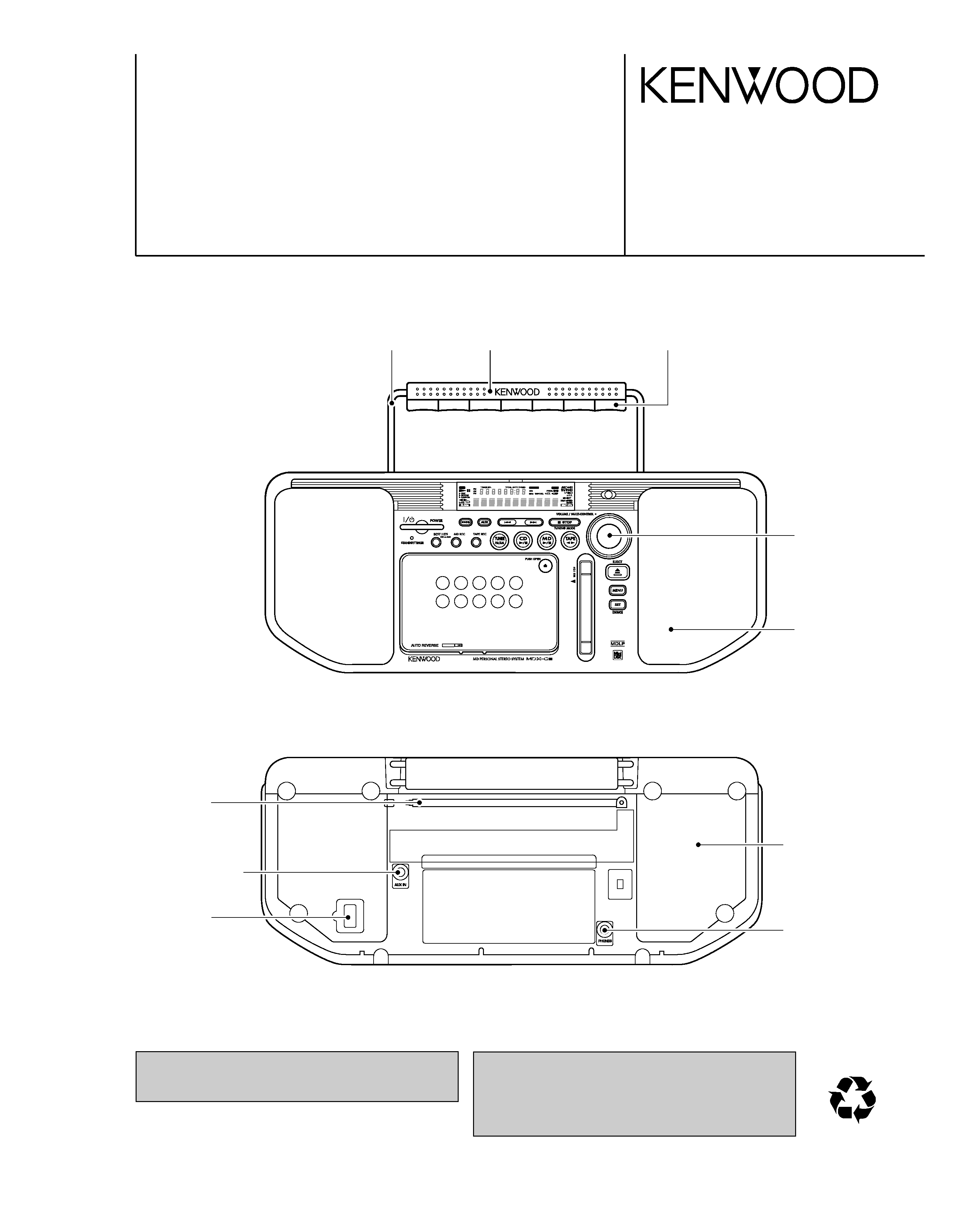
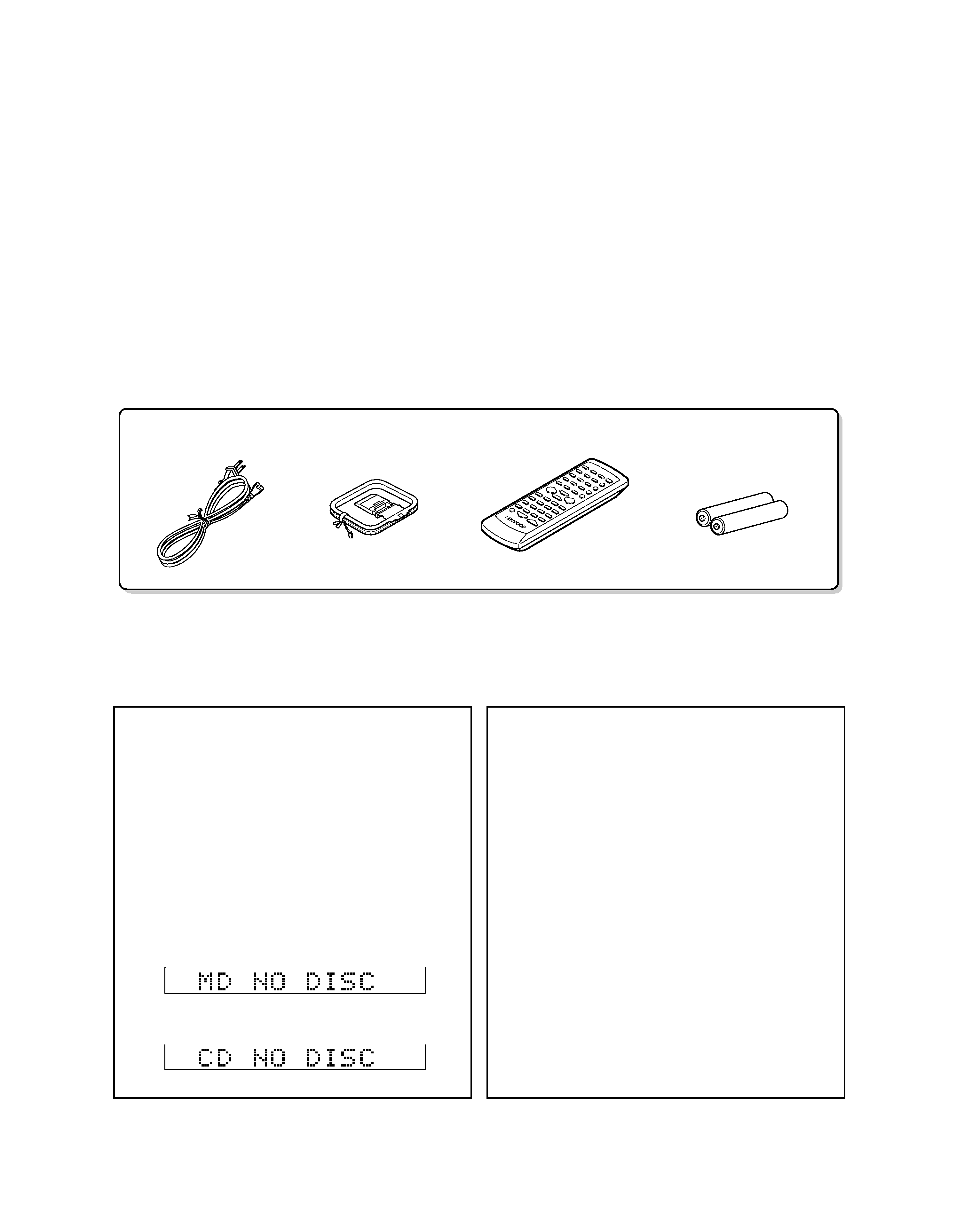
KENWOOD MDX-G3 Service Manual

Cover page of KENWOOD MDX-G3 Service Manual

Service Manual for KENWOOD MDX-G3, downloadable as a PDF file.

We also have owner's manual to this model.

Manual details

  • Immediate download after payment.
  • Delivered as a PDF file.
  • The manual has 33 pages
  • File size: 4.01 MB
  • Available language versions: English
  • Different language versions may vary sligthly in file size and page count.

We guarantee that...

  • our manuals are complete,
  • the manual includes circuit diagrams,
  • our manuals are checked with antivirus,
  • We'll issue refund if the manual is damaged, incomplete or unreadable (our refund policy)

Sample pages

Thumbnail of page 1Thumbnail of page 2Thumbnail of page 3Thumbnail of page 4
Thumbnail of page 5Thumbnail of page 6Thumbnail of page 7Thumbnail of page 8
Thumbnail of page 9
background image
70%
MD PERSONAL STEREO SYSTEM
MDX-G3
SERVICE MANUAL
© 2001-1/B51-5697-00 (K/K) 329
APE
T
Dressing panel
(A21-3897-03): L
(A21-3926-03): SR
Arm
(D10-3983-04)
Handle
(K01-0127-03): L
(K01-0143-03): SR
Knob ass'y
(K29-7870-04): L
(K29-7918-04): SR
Panel ass'y
(A60-1975-11): L
(A60-1982-11): S
(A60-1986-11): R
In compliance with Federal Regulations, following are repro-
duction of labels on, or inside the product relating to laser
product safety.
KENWOOD-Crop. certifies this equipment conforms to DHHS
Regulations No.21 CFR 1040. 10, Chapter 1, subchapter J.
DANGER : Laser radiation when open and interlock defeat-
ed.
AVOID DIRECT EXPOSURE TO BEAM.
L: BLUE, S: SILVER, R: RED
Note: Please contact KENWOOD service in your side if
you want to get the AC power cord.
Plastic cabinet ass'y
(A02-2996-01)
Miniature phone jack
(E11-0399-05)
Rod antenna
(T90-0828-05)
Miniature phone jack
(E11-0399-05)
AC inlet
(E03-0374-05)
background image
POWER cord (1)
(E30-2927-05)
Remote control unit (1)
Battery cover (A09-1151-08)
(A70-1449-05)
Batteries(R6/AA)
for remote (2)
AM loop antenna (1)
(T90-0865-05)
MDX-G3
2
CONTENTS / ACCESSORIES / CAUTIONS
CONTENTS / ACCESSORIES / CAUTIONS ............. 2
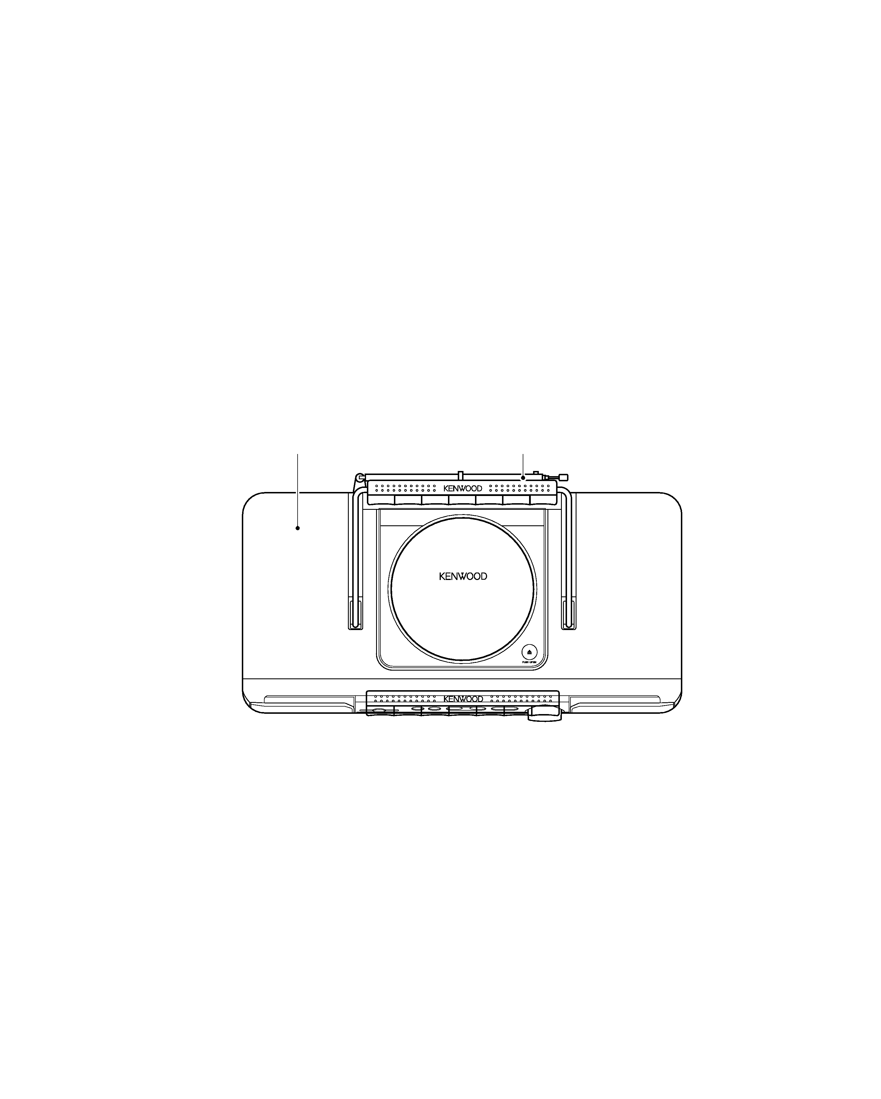
EXTERNAL VIEW .......................................................3
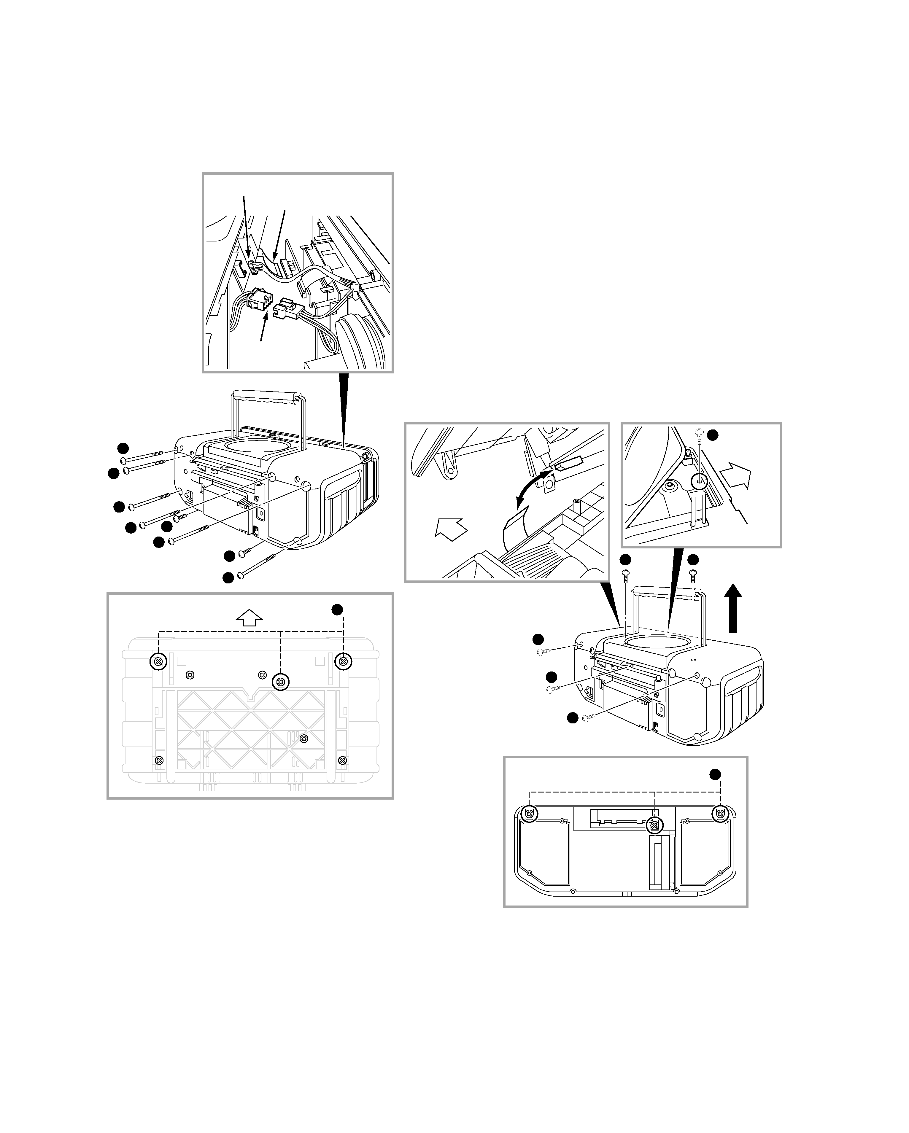
DISASSEMBLY FOR REPAIR....................................4
CIRCUIT DESCRIPTION ............................................5
ADJUSTMENT ..........................................................10
WIRING DIAGRAM ...................................................12
PC BOARD .............................................................. 13
SCHEMATIC DIAGRAM .......................................... 16
EXPLODED VIEW ....................................................29
PARTS LIST..............................................................31
SPECIFICATIONS ....................................................39
Contents
Accessories
Operation to reset
The microcomputer may fall into malfunction when a cord is
unplugged and plugged again while the unit is ON or due to an
external cause. In such a case, the microcomputer should be reset
as described below:
Unplug the power cord from the wall outlet and, while holding the
POWER key depressed, plug the power cord again. This initializes
the microcomputer. Note that this clears the previously stored
memory.
Note related to transportation and move-
ment
Before transporting or moving this unit, carry out the following oper-
ations.
1. Remove the CD or MD from the unit.
2. Press the MD
6 key.
3. Wait for some time and verify that the display becomes as
shown in the figure.
4. Press the CD
6 key.
5. Wait for some time and verify that the display becomes as
shown in the figure.
6. Wait a few seconds and turn the unit off.
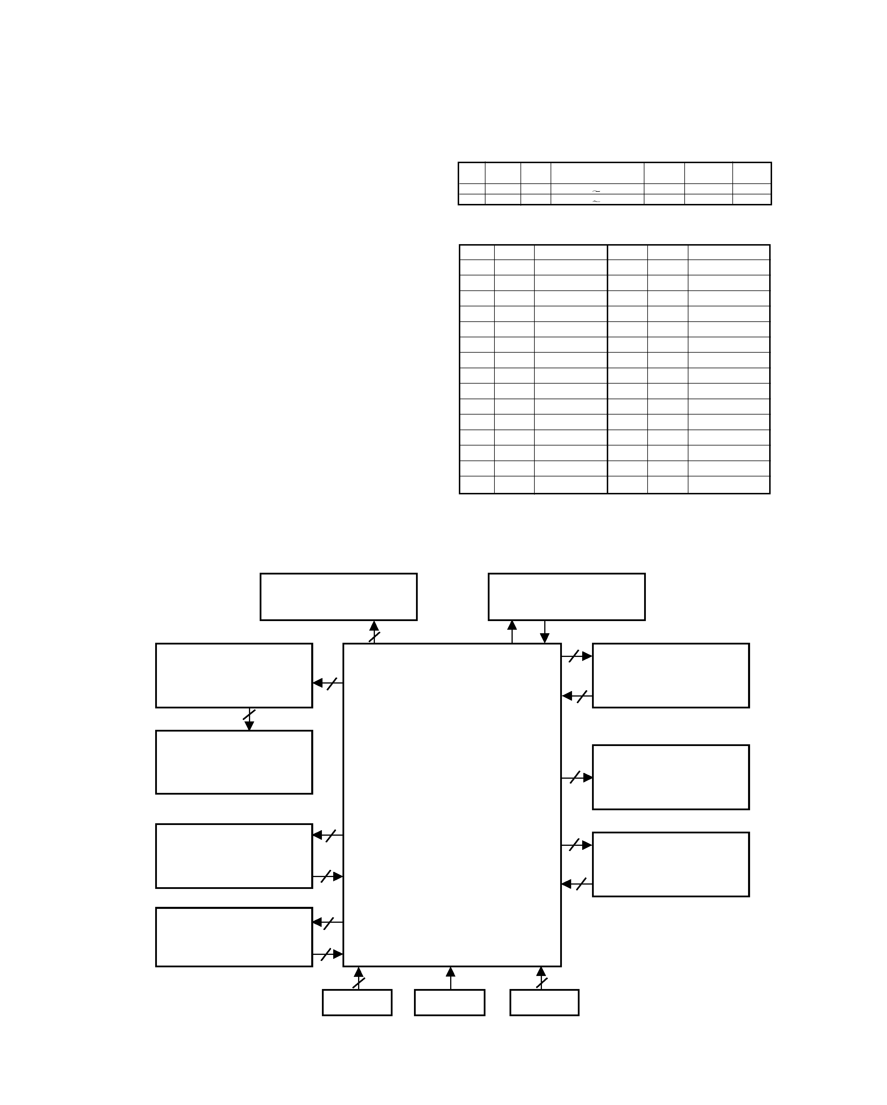
Memory backup function
Stored contents which are cleared immediately when power plug is
unplugged from power outlet.
- Clock display(Backed up for 3 min.)
Stored contents which are cleared in at least a day after power
plug is unplugged from power outlet.
¶ Amplifier section
- Input selection
- Volume control value
- AUX input level
- Tone control levels
- Timer setting contents
¶ Tuner section
- Receiving band
- Frequency
- Preset stations
- Auto tuning setting
¶ Cassette deck
- Tape transport direction
- Tape equalizer
- Tape reverse mode
¶ MD recorder
- Recording mode
- Recording speed
Cautions
background image
MDX-G3
3
EXTERNAL VIEW
CD/MD HIGH SPEED DUBBING SYSTEM
1
B
I T
D
U A
L D / A C O N
V E
R
T
E
R
Rod antenna
(T90-0828-05)
Top cover ass'y
(A52-0920-21): L
(A52-0922-21): S
(A52-0924-21): R
background image
MDX-G3
4
DISASSEMBLY FOR REPAIR
SP CONNECTOR
X09 (G/7) -CN502
X28-CN1
1
1
1
1
2
1
1
2
2 x3
FRONT SIDE
4
3
3
3
5
4
4
FRONT SIDE
FRONT SIDE
FRONT SIDE
x3
1. How to Remove Front Panel
1. Remove 6 screws(
1) from the rear side.
2. Remove 2 screws(
2) from the bottom side.
3. Slide the front panel frontwards and pull out the connec-
tors and FPC.
4. Remove the front panel from the rear cabinet.
2. How to Remove Top Panel
1. Remove 3 screws(
3) from rear side.
2. Remove 3 screws(
4) from top side.
3. Remove 3 screws(
5).
4. Lift the top cover.
Note: You need to pull out FPC on the rear side of top cover.
background image
MDX-G3
5
CIRCUIT DESCRIPTION
4. Microprocessor : MN101C49KLA(X09,IC11)
4-1 Microprocessor Periphery Block Diagram
1. Initializing
1-1 Initialization Method
· While pressing the [POWER] key, turn the AC on.
1-2 Initialization Operation
· During the initial operation, the display shows "INITIAL-
IZE "and after that it will be retuned to standby condi-
tion.
· If any mechanisms error occurred, the error indication
is displayed as "ERR" on the display.
1-3 Mechanism Initialization
1 CD Mechanism
· If a mechanism error occurred, the error indication is
displayed as "C ERR" on the display.
2 Deck Mechanism
· If a mechanism error occurred, the error indication is
displayed as "T ERR" on the display.
3 MD Mechanism
· If a mechanism error occurred, the error indication is
displayed as "M ERR" on the display.
· The disc will be unloaded from MD mechanism auto-
matically, if a disc is its in.
P.CH Band
Frequency
P.CH
Band
Frequency
1
FM
98.30MHz
16
FM
98.00MHz
2
FM
87.50MHz
17
FM
98.50MHz
3
FM
108.00MHz
18
FM
87.50MHz
4
FM
89.10MHz
19
AM
990kHz
5
FM
90.00MHz
20
FM
97.70MHz
6
FM
87.50MHz
21
AM
531kHz
7
FM
87.50MHz
22
FM
87.50MHz
8
FM
87.50MHz
23
FM
87.50MHz
9
AM
1602kHz
24
FM
87.50MHz
10
AM
999kHz
25
FM
87.50MHz
11
AM
630kHz
26
FM
87.50MHz
12
AM
1440kHz
27
FM
87.50MHz
13
FM
106.0MHz
28
FM
87.50MHz
14
AM
531kHz
29
FM
108.0MHz
15
FM
87.50MHz
30
AM
945kHz
Set
Destin-
Band
Receiving
Channel
IF
RF
ation
Frequecy Range
Space
M
E1
FM
87.5MHz
108.0MHz
50kHz
+10.7MHz
25kHz
M
E1
AM
531kHz
1602kHz
9kHz
+450kHz
9kHz
2. Tuner Destination
3. Tuner Preset Frequency
X28,IC1
6
3
4
5
51
X09,ED501
X09,IC1
2
X09,IC21
MN101C49KLA
X09,IC22
X09,IC32
6
3
3
3
2
2
KEY1,2
X09,A501
X09,S517
DECK MECHA.
(ADR-2176TR3)
DECK SYSTEM IC
DOT DRIVER
(M66004-001FPG)
Vaccume Fluorescent
Display (HNA-16MM30T)
ENCODER
REMOTE
KEY
MD MECHA
MDM-07
SYSTEM IC
(M61510FP)
CD MECHA
(KSM213CDM)
PLL IC
(LC72131)
DSP IC
(MN662748RPMFA)

Reviews

There are no reviews of this manual yet.