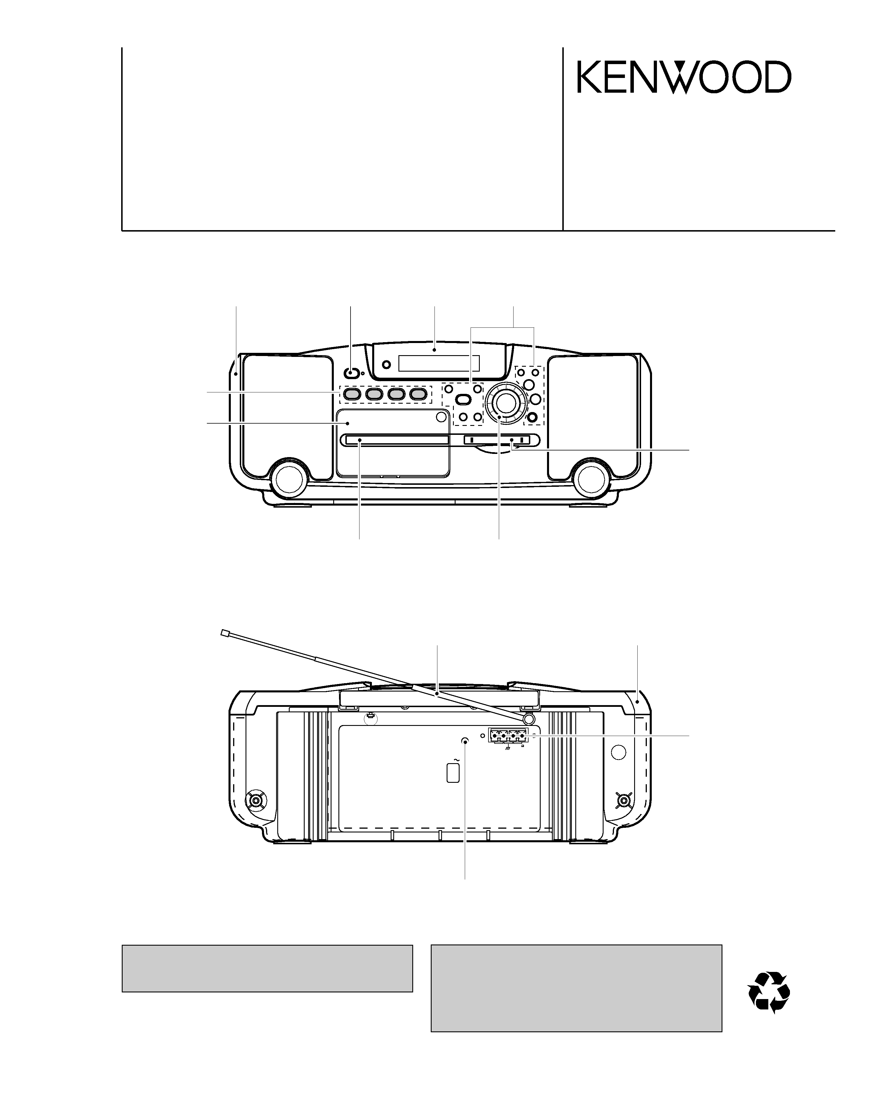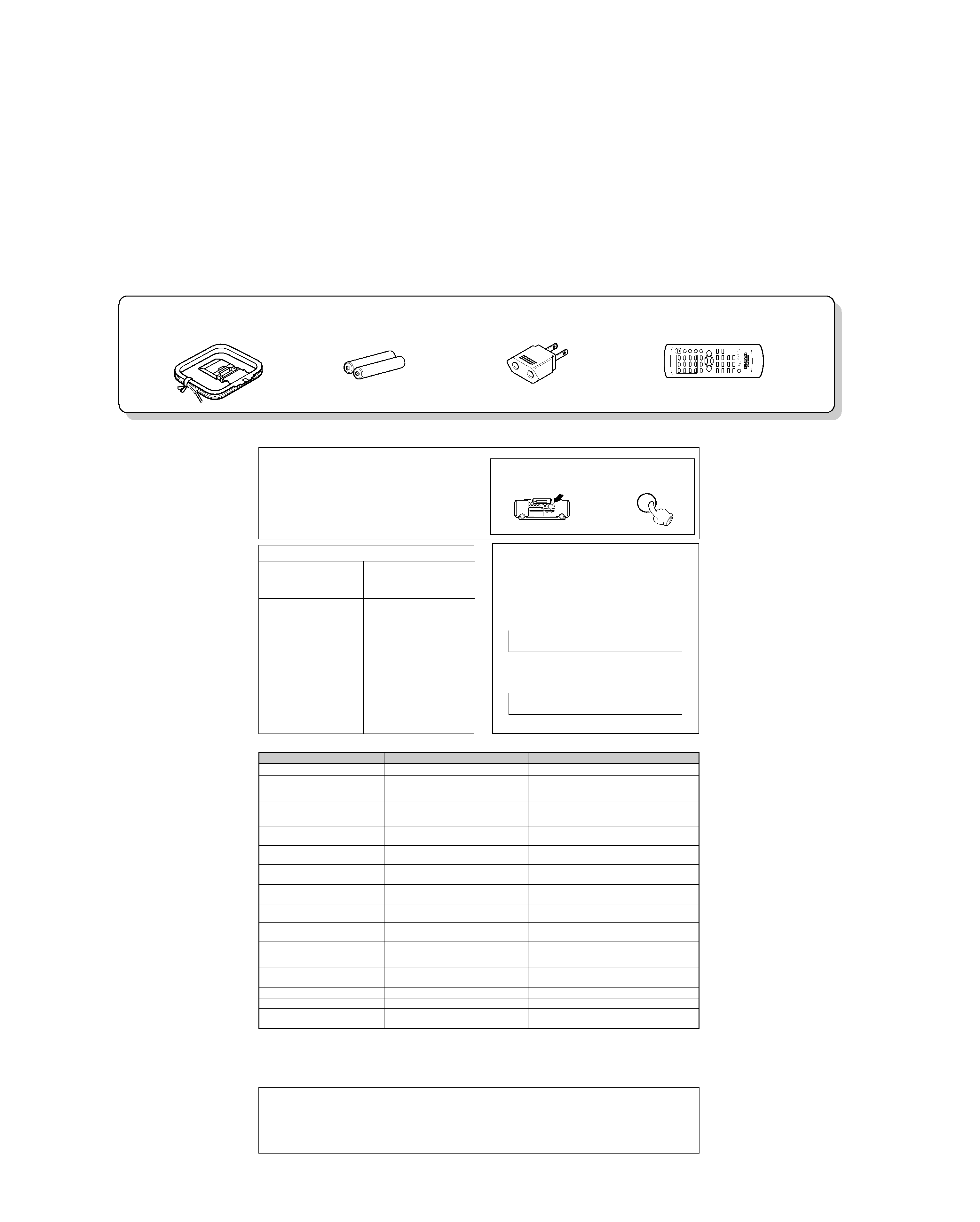
Loop antenna (1)
(T90-0852-05)
Remote control unit (1)
(A70-1325-05): RC-MDX0101
Battery cover (A09-1151-08)
R6/SUM-3 batteries
for remote (2)
AC plug adaptor (1)
(E03-0115-05)
MDX-F1
2
CONTENTS / ACCESSORIES / CAUTIONS
CONTENTS / ACCESSORIES / CAUTIONS ............. 2
CONTROLS ................................................................3
DISASSEMBLY FOR REPAIR....................................4
CIRCUIT DESCRIPTION ............................................5
ADJUSTMENT ..........................................................16
PC BOARD .............................................................. 20
SCHEMATIC DIAGRAM .......................................... 26
EXPLODED VIEW ....................................................38
PARTS LIST..............................................................40
SPECIFICATIONS ......................................Back cover
Contents
Accessories
Cautions
Stored contents which are
cleared immediately when
power plug is unplugged
from power outlet
Stored contents which are
cleared in at least a day
after power plug is
unplugged from power
outlet
Clock display
MD recorder section
Amplifier section
"on/standby" status
(ON or STANDBY)
Input selection
Volume control value
Tone control levels
Tuner section
Receiving band
Frequency
Preset stations
Auto tuning setting
Cassette deck unit
Transport direction
DOLBY NR
Reverse mode
Timer setting contents
Memory backup function
Note related to transportation and movement
Before transporting or moving this unit, carry out the f
ollowing operations.
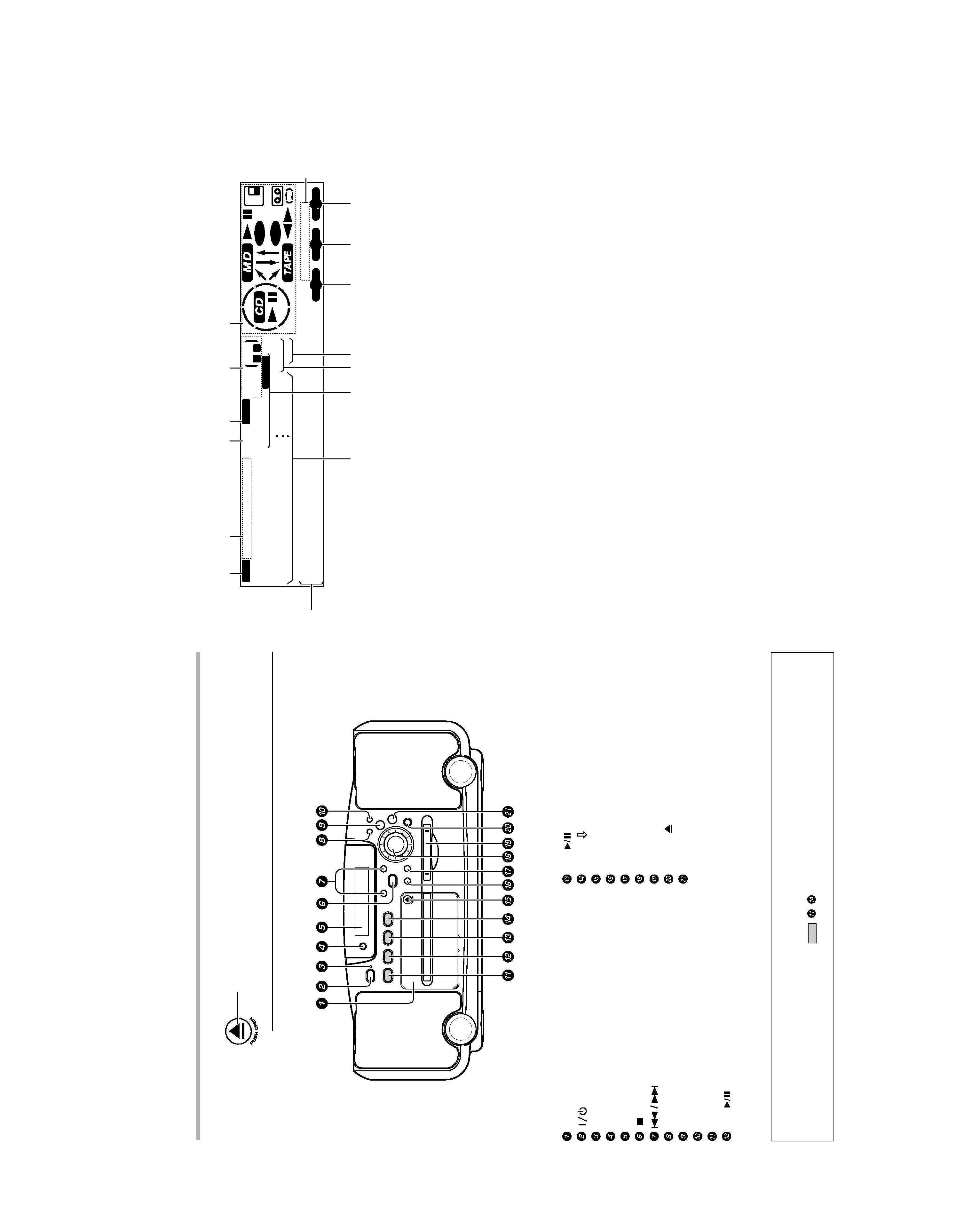
1 Remove the CD or MD from the unit.
2 Press the 6 key of the MD.
3 Wait for some time and verify that the display
becomes as shown in the figure.
4 Press the 6 key of the CD.
5 Wait for some time and verify that the display
becomes as shown in the figure.
6 Wait a few seconds and turn the unit OFF.
MD
NO
DISC
CD
NO
DISC
Operation to reset
The microcomputer may fall into malfunction (impossibility
to operate, erroneous display, etc.) when the power cord
is unplugged while unit is ON or due to an external factor.
In this case, execute the following procedure to reset the
microcomputer and return it to normal condition.
Unplug the power cord from the power outlet then,
while holding the REPEAT key depressed, plug the
power cord again.
÷ Please note that resetting the microcomputer clears
the contents stored in and it returns to condition
when it left the factory.
0
REPEAT
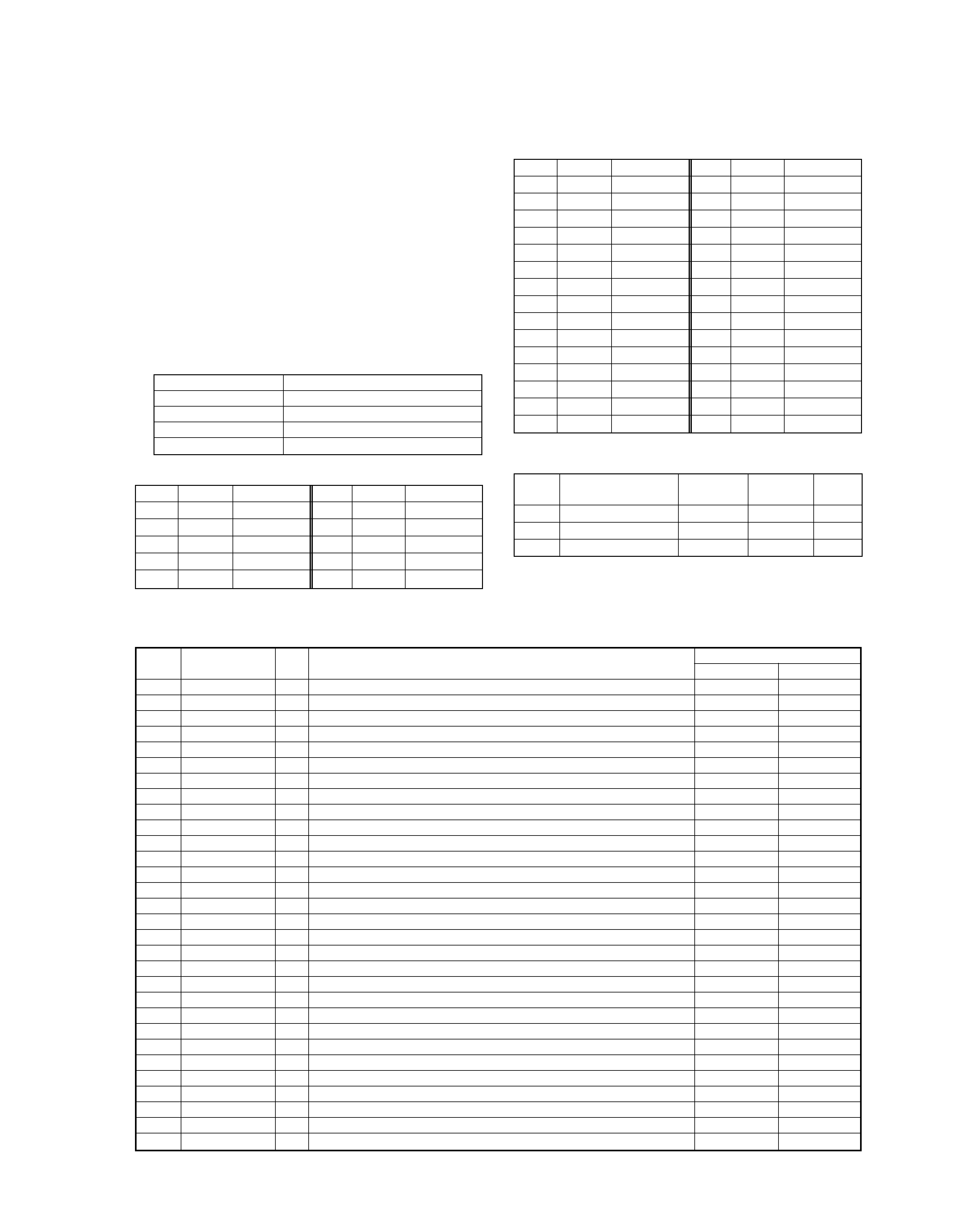
Action
Meaning
Displayed Message
÷ No disc is placed on the tray.
÷ An attempt is made to record digital
signal from a source while its digital copy
has been prohibited by SCMS.
÷ There is no recordable area on the disc.
÷ An attempt is made to record a 256th
track.
÷ An attemptis made to assign a titlewith
more characters than usable.
÷ The disc does not contain any record-
ings.
÷ The disc does not contain any tracks but
has a disc title.
÷ The TOC *1 data of the disc is being
read.
÷ The data related to editing or recording is
being writtenin the disc.
÷ The contents of UTOC *2 are abnormal.
÷ An attempt is made to perform editing
beyond the restrictions, for example to
erase a track which is too short.
÷ This is a message for confirming if edit-
ing can really be executed.
÷ The minidisc is write-protected.
÷ The minidisc is only for playback.
÷ This indicates some trouble.
÷ Load a disc.
÷ Recording is not possible.
÷ Use another recordable disc.
÷ Morethan 256 tracks cannot be recorded
per disc.
÷ Refer to "Total number of title characters".
÷ When playback is required, use a recorded
disc.
÷ The disc can be used for recording without
any problem.
÷ This is a normal operation.
÷ This is a normal operation.
÷ Perform "ALLERASE" operation. If this
is not possible, use another disc.
÷ Perform editing following the restrictions.
÷ Press the ENTER key to execute editing.
÷ Cancel the write protection.
÷ Insert a minidisc for recording.
÷ Return to normal condition is made by
switching the unit off and then on again.
NO DISC
CAN'T COPY
DISC FULL
TITLE FULL
BLANK DISC
NO TRACKS
READING
WRITING
DISC ERROR
CAN'T EDIT
?(blinking)
PROTECTED
PLAY ONLY
UNIT ERROR
MD recorder section (Displayed messages and actions to be taken against them)
*1All minidiscs contain a Table of Contents (TOC) in addition to sound signals. The TOC is similar to the table of contents
in a book and contains information, such as track numbers, track length, and character information, that cannot be
rewritten.
*2In addition to the TOC, minidiscs also contain a special User's Table of Contents (UTOC) that contains track number, track
length, and character information, that can be rewritten.
Memory Backup for the MD Recorder Section
The contents of the memory are not stored on the disc if the power cord is unplugged.
If the power cord is unplugged suddenly or there is a power failure, the information on recording and editing
(normally recorded when the minidisc is ejected) may be erased or destroyed before it is recorded on the
minidisc. Once the information has disappeared, it can not be recovered.
After recording or editing, always remove the minidisc to record the recording or editing information.