DMF-3020/3020
(S)/5020/MD-203
4
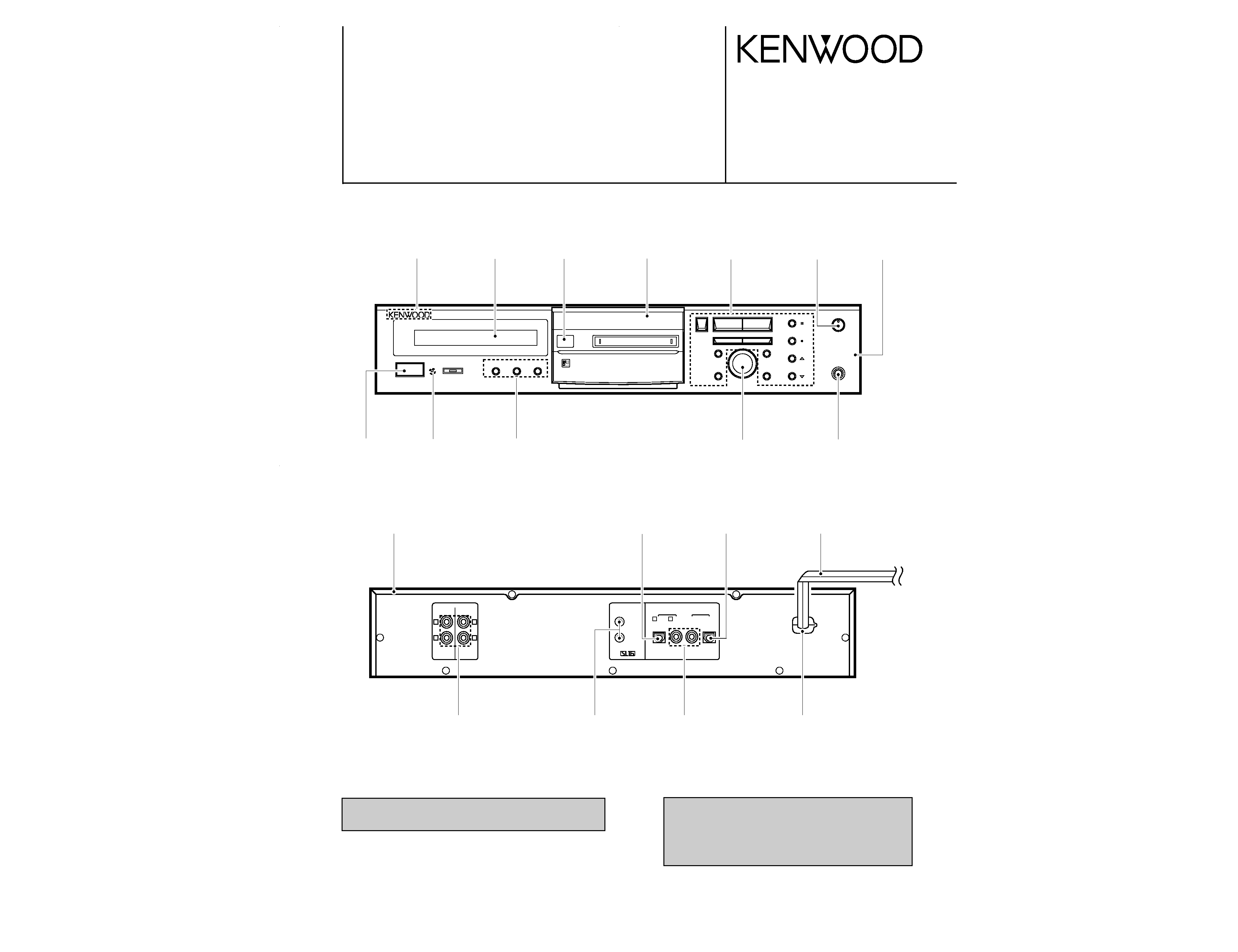
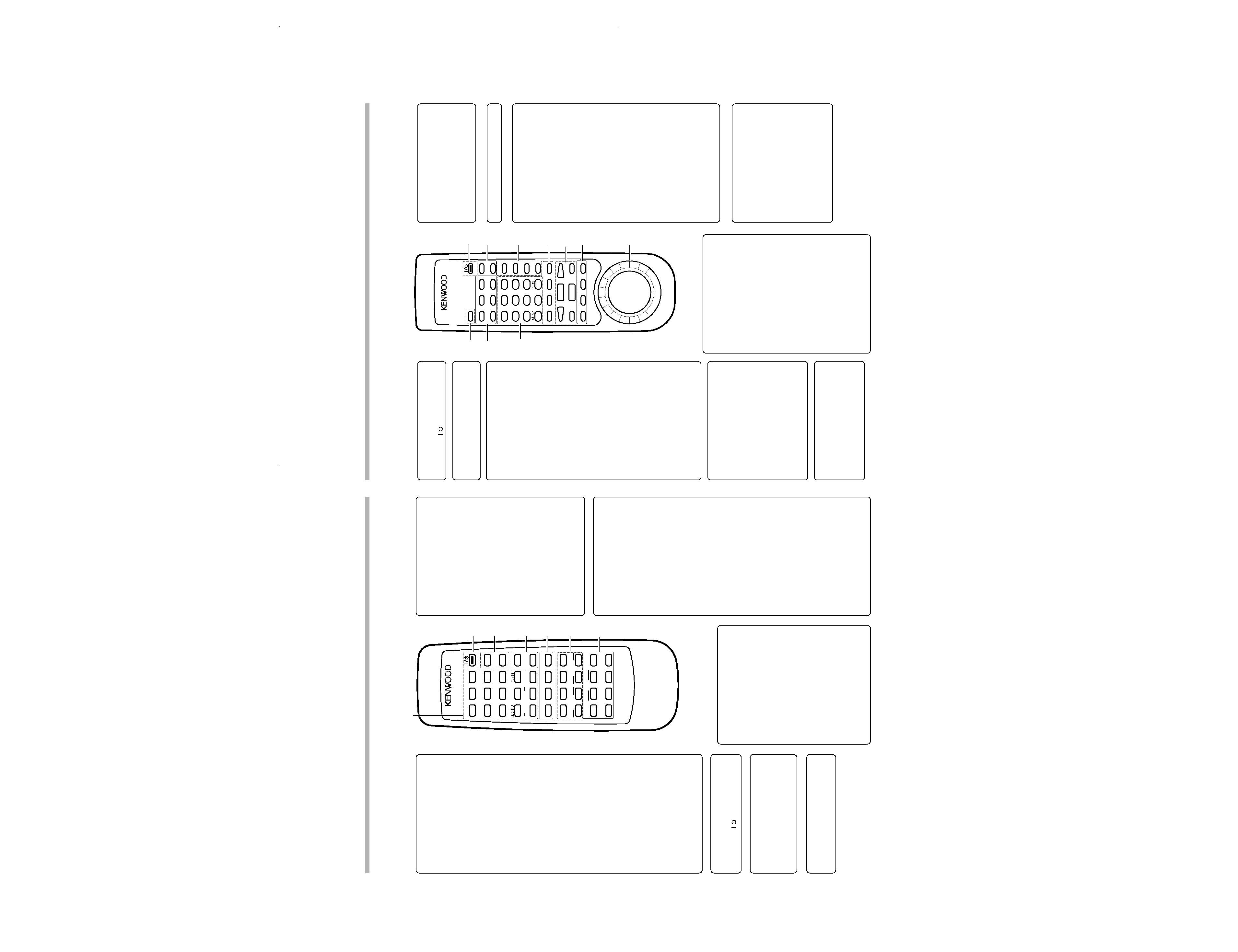
CONTROLS
1Numeric keys / Character editing keys
Numeric keys
0-9
: Press when selecting a track number
directly.
+10
: Press when selecting a track number
10 or more.
+100
: Press when selecting a track number
100 or more.
: These keys are also used to select a
character or symbol during title editing.
CHARACTER DELETE / CLEAR key
CHARACTER DELETE
: During title input, press to delete a
character.
CLEAR
: During editing, press to clear a selected
track number.
: In program mode, press to clear the
program.
CHARACTER SPACE / CHECK key
CHARACTER SPACE
: During title input, press to insert a blank
space character.
CHECK
: In program mode, press to check the
program contents.
CHARA. (Character)/ P.MODE (Play
Mode) key
CHARA.
: Press to select a character group dur-
ing the title input operation.
P.MODE
: Press to initiate the program mode.
5Editing mode keys
REC INPUT key
: Press to switch the recording input line
between digital (optical/coaxial), analog
and monaural.
EDIT key
: Press to switch the editing mode ON/
OFF.
SET key
: This key is used in the title assignment or
editing operations.
: When pressed in the recording pause
mode, the MEMORY REC function is set
and recording starts from the sound ap-
proximately 6 seconds before the cur-
rent sound.
ENTER key
: Press to execute editing or enter the
input title in memory.
7Applied operation keys
EDIT CANCEL key
: Press to cancel the editing operation.
TITLE INPUT key
: Press to switch the title input mode ON/
OFF.
TITLE SEARCH key
: Press to switch the title search mode
ON/OFF.
: During title editing, press to switch the
title change input mode between the
"overwrite mode" and "insert mode".
TIME DISPLAY key
: Press to switch the time and title display
modes.
AUTO PAUSE key
: When this key is pressed, the pause
mode is initiated automatically at the
point where the track number changes
during playback.
: When pressed in the recording or record-
ing standby mode, the AUTO REC PAUSE
mode is turned on.
AUTO/MANU. key
: Selects whether the track numbers are
to be marked automatically during re-
cording (AUTO) or to be marked manu-
ally after it (MANUAL).
MONITOR key
: Press to monitor the sound being input
from the source while the unit is in stop
mode.
METER MODE key
: Press to switch the level meter display
contents.
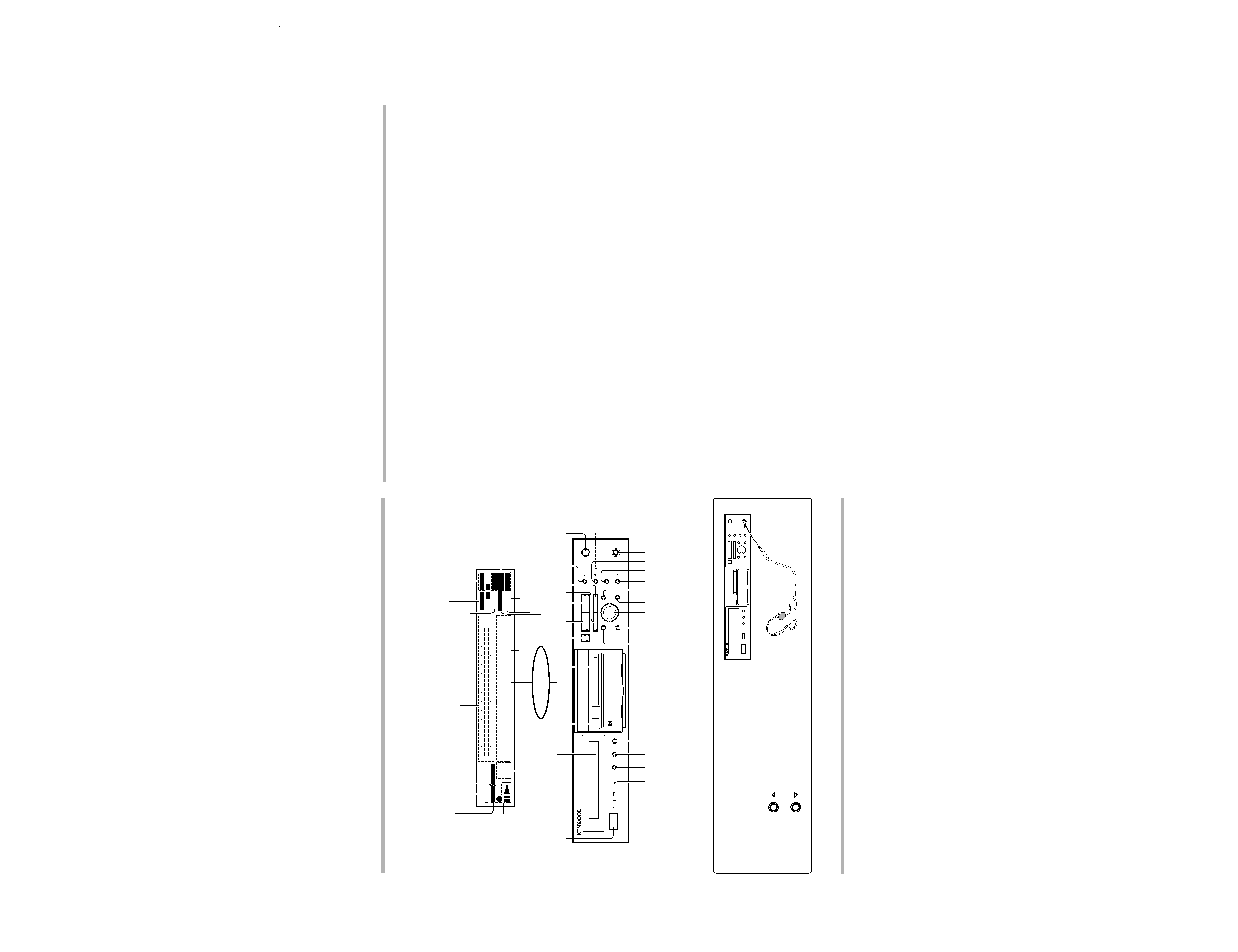
Remote control unit (DMF-3020/MD-203)
The remote control unit incorporates the basic operation keys as well as a variety of applied operation keys so that it can be
used in a wide range of purposes.
The keys on the remote control unit with the same names as on the main unit have the same function as the keys
on the main unit.
Model: RC-M0302
Infrared ray system
3REPEATkey
: Press to switch the repeat modes for
repeat playback.
RANDOM key
: Press to initiate the random play mode.
2ON/STANDBY key
: Press to turn the unit between ON and
STANDBY ( /
) modes.
6Basic operation keys
: Record key
8
: Pause key
7
: Stop key
3
: Play key
CURSOR /
1 , ¡ keys
1 , ¡
: During playback, press to fast forward
or fast reverse the play.
CURSOR
: During title input, press to move the
cursor.
CHARACTER/SEARCH/
4 , ¢ keys
CHARACTER
: Press to select a character group dur-
ing the title input operation.
SEARCH
: During title search, rotate to select a
track number.
4 , ¢
: During playback, press to skip tracks in
the forward or reverse direction.
ABC
1
DEF
23
JKL
MNO
5
GHI
46
TUV
WXY
8
PRS
79
POWER
EDIT
CANCEL
QZ
0
+100
+10
RANDOM
REPEAT
SPACE
CHARA.
CHECK
DELETE
CLEAR
P.MODE
EDIT
SET
REC INPUT
ENTER
87
¡
14
¢
AUTO
PAUSE
AUTO
/MANU.
METER
MODE
TIME
DISPLAY
OUTPUT
LEVEL
MONITOR
REMOTE CONTROL UNIT
RC-M0302
CURSOR
TITLE
CHARACTER
/SEARCH
CHARACTER
%
fi
÷
£
INPUT
SEARCH
2
3
4
5
6
7
1
4OUTPUT LEVEL (%fi) keys
: Use these to adjust the output level and
the volume of the headphones.
3Character editing keys
TIME DISPLAY key
: Press to switch the time and title display
modes.
CHARA. (Character)/ P.MODE (Play
Mode) key
CHARA.
: Press to select a character group dur-
ing the title input operation.
P.MODE
: Press to initiate the program mode.
DELETE / CLEAR key
DELETE
: During title input, press to delete a
character.
CLEAR
: During editing, press to clear a selected
track number.
: In program mode, press to clear the
program.
SPACE / CHECK key
SPACE
: During title input, press to insert a blank
space character.
CHECK
: In program mode, press to check the
program contents.
8EJECT (0) key
9Editing mode keys
EDIT CANCEL key
: Press to cancel the editing operation.
TITLE INPUT key
: Press to switch the title input mode ON/
OFF.
TITLE SEARCH key
: Press to switch the title search mode
ON/OFF.
: During title editing, press to switch the
title change input mode between the
"overwrite mode" and "insert mode".
SET key
: This key is used in the title assignment or
editing operations.
: When pressed in the recording pause
mode, the MEMORY REC function is set
and recording starts from the sound ap-
proximately 6 seconds before the cur-
rent sound.
ENTER key
: Press to execute editing or enter the
input title in memory.
EDIT key
: Press to switch the editing mode ON/
OFF.
Remote control unit (DMF-5020)
The remote control unit incorporates the basic operation keys as well as a variety of applied operation keys so that it can be
used in a wide range of purposes.
The keys on the remote control unit with the same names as on the main unit have the same function as the keys
on the main unit.
Model: RC-M0705
Infrared ray system
4MONITOR key
: Press to monitor the sound being input
from the source while the unit is in stop
mode.
METER key
: Press to switch the level meter display
contents.
RANDOM key
: Press to initiate the random play mode.
REPEAT key
: Press to switch the repeat modes for
repeat playback.
1ON/STANDBY key
: Press to turn the unit between ON and
STANDBY ( /
) modes.
6Recording-related keys
REC MODE key
: Press to switch the recording setting ad-
justment modes ON/OFF.
AUTO/MANU. key
: Selects whether the track numbers are
to be marked automatically during re-
cording (AUTO) or to be marked manu-
ally after it (MANUAL).
AUTO PAUSE key
: When this key is pressed, the pause
mode is initiated automatically at the
point where the track number changes
during playback.
: When pressed in the recording or record-
ing standby mode, the AUTO REC PAUSE
mode is turned on.
REC INPUT key
: Press to switch the recording input line
between digital (optical/coaxial), analog
and monaural.
EDIT CANCEL
MONITOR
÷
0
REC MODE
SET
1
GHI
4
PRS
7
+100
METER
AUTO/MANU.
INPUT
ABC
ENTER
2
JKL
5
TUV
8
QZ
0
RANDOM
AUTO PAUSE
SEARCH
DEF
EDIT
3
MNO
6
WXY
9
+10
REPEAT
8
REC INPUT
%
fi
CHARA.
DELETE
SPACE
TITLE
TMTM/CUR.L
CUR.R/
££
TIME
DISPLAY
OUTPUT
LEVEL
POWER
REMOTE CONTROL UNIT
RC-M0705
4
¢
£
7
CLEAR
CHECK
P.MODE
8
9
1
2
3
4
5
6
7
0
5Basic operation keys
3
: Play key
4 , ¢ : Skip down/up keys
: Record key
7
: Stop key
8
: Pause key
7CURSOR / 1 , ¡ shuttle
CURSOR
: During title input, rotate to move the
cursor.
1 , ¡
: Use this during playback for forward and
reverse search.
2OUTPUT LEVEL (%fi) keys
: Use these to adjust the output level and
the volume of the headphones.
0Numeric keys
0-9
: Press when selecting a track number
directly.
+10
: Press when selecting a track number 10
or more.
+100
: Press when selecting a track number
100 or more.
: These keys are also used to select a
character or symbol during title editing.
DMF-5020(K)
COVER1,1P(
98.12.9
16:39
y[W
7