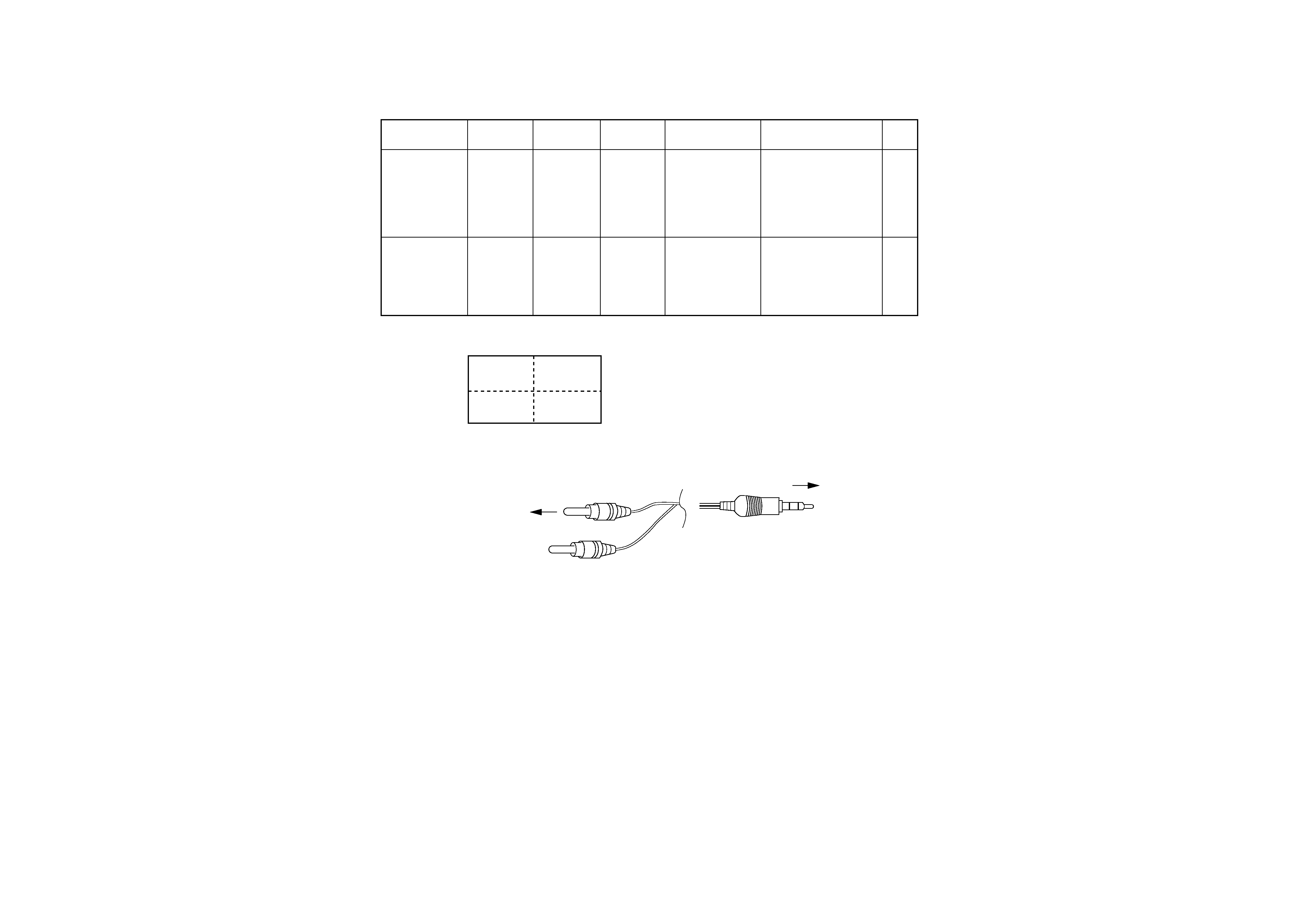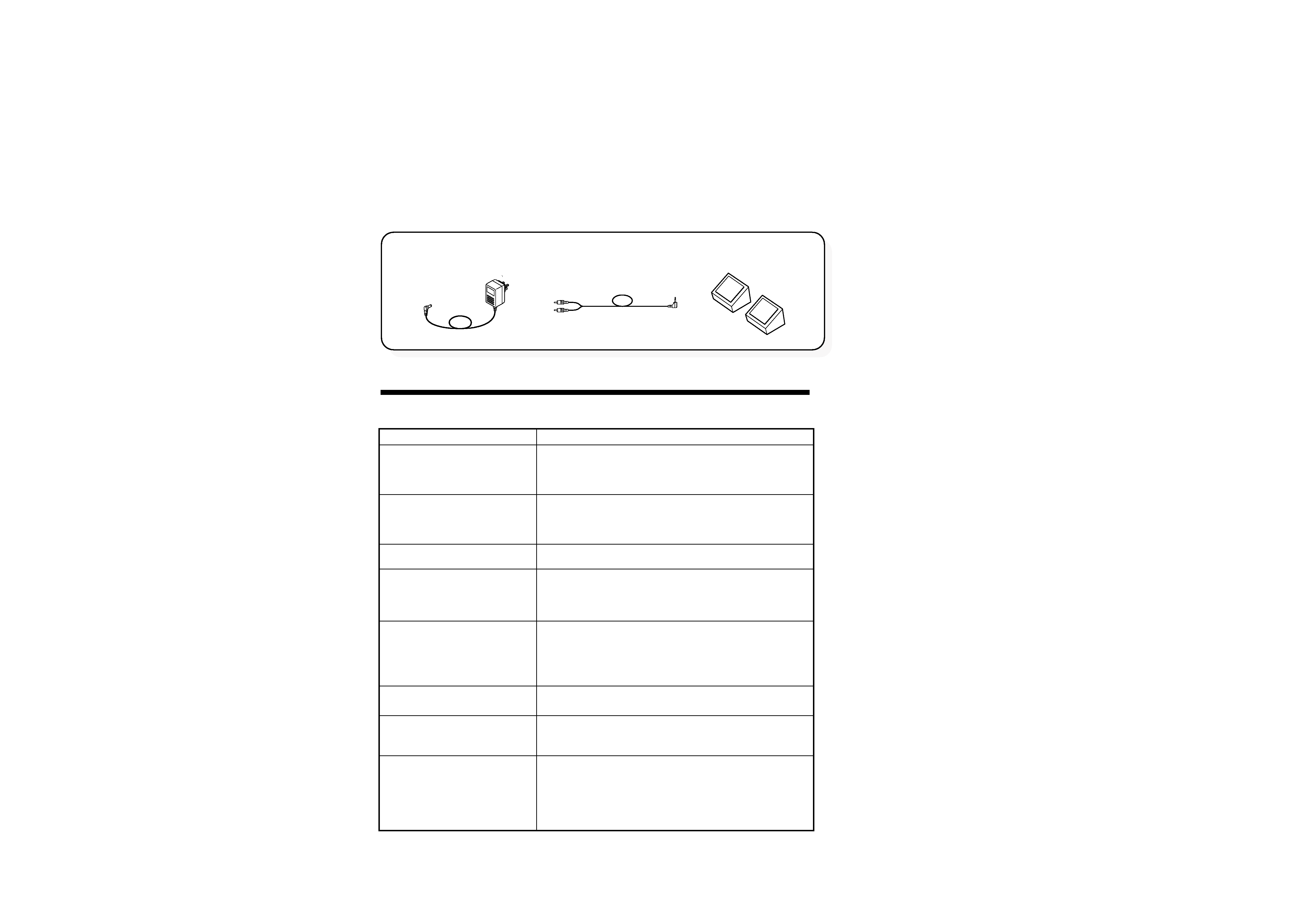
AV cable (1)
AC adaptor (1)
(W08-0687-08): T
(W08-0688-08): E
(E30-7241-08)
(J39-1039-08)
Cushion (2)
Action to be taken
Check the AC adaptor for proper connection.
Check that the POWER switch is turned on.
Check that the brightness and volume are
minimized or the system is put in mute state.
Check the selected A V input (AV1 or AV2) for
connection to A V equipment.
Check for reception of audio/video signals fr om AV
equipment.
Check the brightness for maximum or minimum.
Check the sound volume for minimum or check
the system for being put in mute state.
Check headphones for being plugged into the
system.
Check for reception of radio interference from
other equipment, etc. (T urn of f the power of other
equipment.)
Check COLOR, TINT, and PICTURE for proper
adjustment.
Check the direction of the crystal liquid panel for
proper adjustment.
Check the brightness for proper adjustment.
When the temperatur e of the system is low , the
screen becomes darker than usual just after the
power is turned on because of the characteristic of
the liquid cr ystal panel. W ait for a while until the
temperature goes up. The screen will get light as
usual.
Problem
No image and no sound
No image and no sound ( NO
SIGNAL appears)
No image, or black or white
screen
No Sound
Poor-quality image displayed
Image doubly displayed
Image fading
Image swaying
Stripes and patterns
Inappropriate
color or light color
Dark screen
Dark screen in the initial stage
Troubleshooting Problems
If the system does not work as you expect, perform the following checks before contacting
Customer Support.
If this product interferes with radio reception during use, place it far enough away from the
radio to eliminate the interference.
·
·
·
·
·
·
·
·
·
·
·
·
·
·
·
·
·
·
KVX-5-L/-S
2
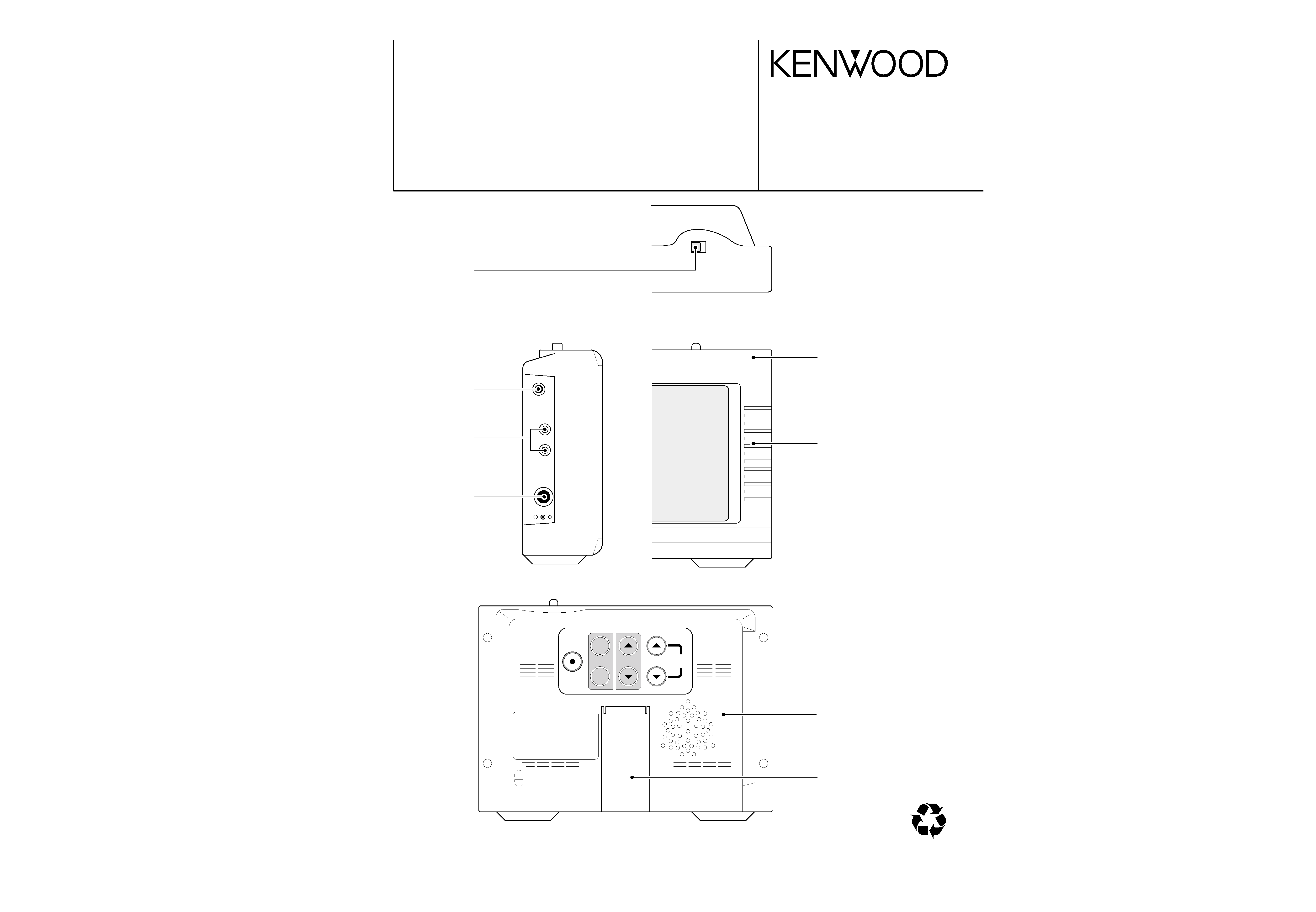
CONTENTS / ACCESSORIES
CONTENTS / ACCESSORIES ...................................2
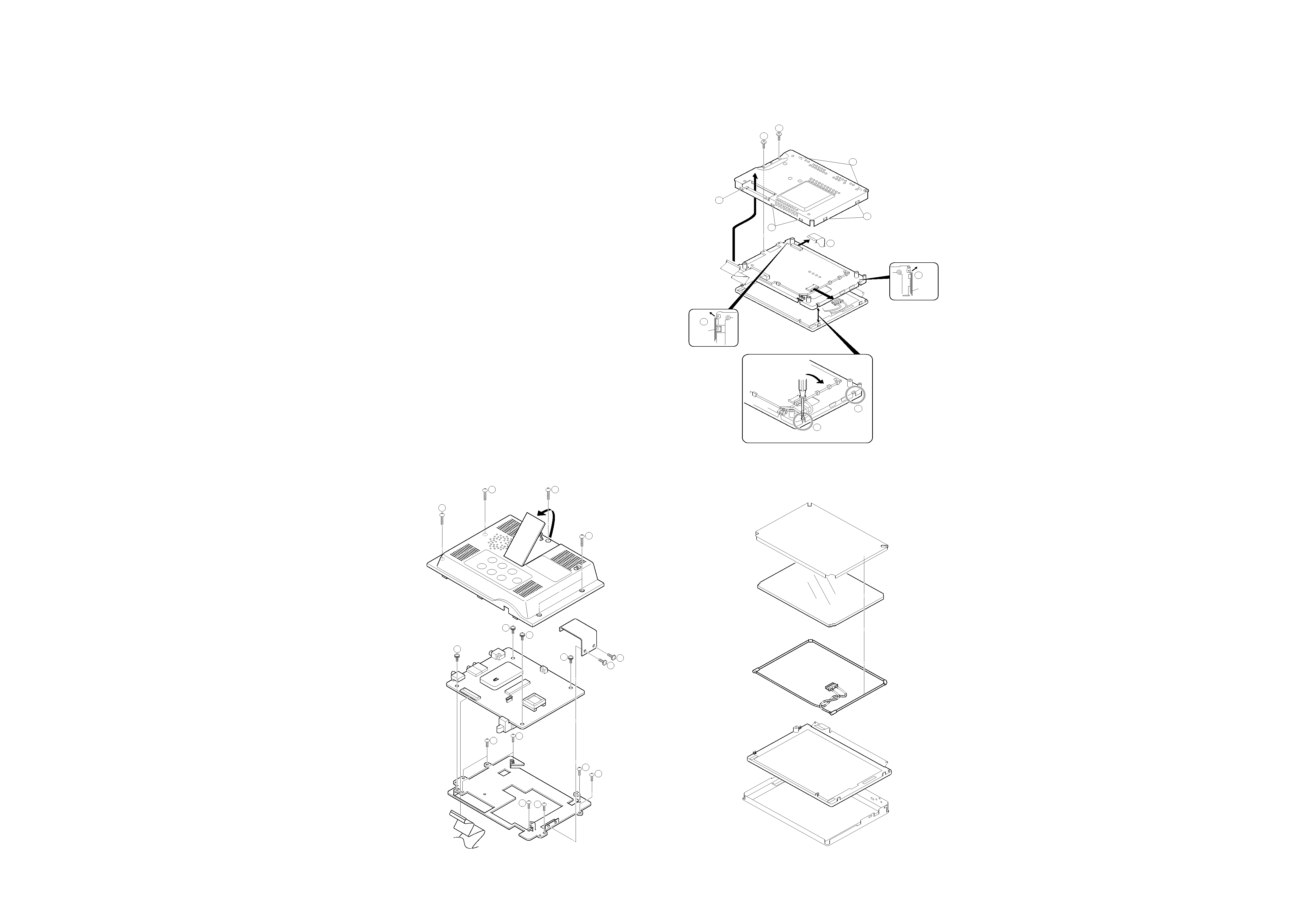
DISASSEMBLY FOR REPAIR....................................3
ADJUSTMENT ............................................................4
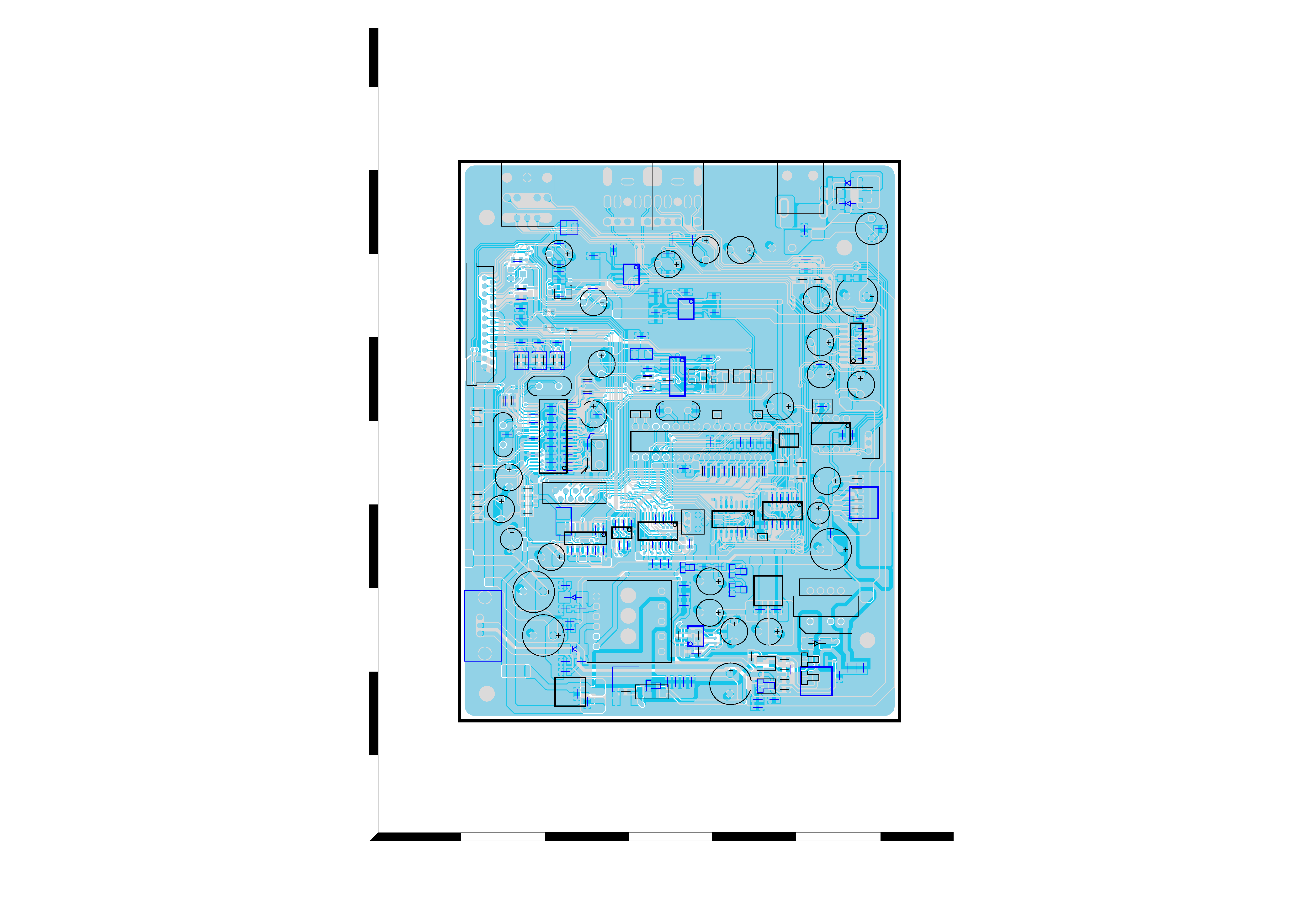
PC BOARD .................................................................5
SCHEMATIC DIAGRAM .............................................7
EXPLODED VIEW ......................................................9
PARTS LIST..............................................................10
PARTS DESCRIPTIONS ..........................................13
SPECIFICATIONS .......................................Back cover
Contents
Accessories