KENWOOD KTF-3010 Owner's Manual

Cover page of KENWOOD KTF-3010 Owner's Manual

Owner's Manual for KENWOOD KTF-3010, downloadable as a PDF file.

We also have service manual to this model.

Manual details

  • Immediate download after payment.
  • Delivered as a PDF file.
  • The manual has 20 pages
  • File size: 0.28 MB
  • Available language versions: Japanese, English
  • Different language versions may vary sligthly in file size and page count.

We guarantee that...

  • our manuals are complete,
  • our manuals are checked with antivirus,
  • We'll issue refund if the manual is damaged, incomplete or unreadable (our refund policy)

Sample pages

Thumbnail of page 1Thumbnail of page 2Thumbnail of page 3Thumbnail of page 4
Thumbnail of page 5Thumbnail of page 6Thumbnail of page 7Thumbnail of page 8
Thumbnail of page 9
background image
FM/MW/LW TUNER
B60-3703-00 00 MA ( E2, T )
99/12 11 10 9 8 7 6 5 4 3 2 1 98/12 11 10 9 8 7 6 5 4 3 2 1
KENWOOD CORPORATION
INSTRUCTION MANUAL
KTF-2010
KTF-3010
OC
background image
FM/MW/LW TUNER
B60-3703-00 00 MA ( E2, T )
99/12 11 10 9 8 7 6 5 4 3 2 1 98/12 11 10 9 8 7 6 5 4 3 2 1
KENWOOD CORPORATION
INSTRUCTION MANUAL
KTF-2010
KTF-3010
OC
background image
KTF-3010/KTF-2010 (En)
2
RISK OF ELECTRIC SHOCK
DO NOT OPEN
CAUTION
Before applying power
Units are designed for operation as follows.
Europe , U.K. and Russia ......................................................... AC 230 V only
For the United Kingdom
Factory fitted moulded mains plug
1.The mains plug contains a fuse. For replacement, use only a 13-Amp ASTA-approved (BS 1362) fuse.
2.The fuse cover must be refitted when replacing the fuse in the moulded plug.
3.Do not cut off the mains plug from this equipment. If the plug fitted is not suitable for the power points in your home or the cable is too short to reach
a power point, then obtain an appropriate safety approved extension lead or adapter, or consult your dealer.
If nonetheless the mains plug is cut off, remove the fuse and dispose of the plug immediately, to avoid a possible shock hazard by inadvertent
connection to the mains supply.
IMPORTANT
The wires in the mains lead are coloured in accordance with the following code.
Blue
: Neutral
Brown
: Live
Do not connect those leads to the earth terminal of a three-pin plug.
WARNING : TO PREVENT FIRE OR ELECTRIC SHOCK, DO NOT EXPOSE THIS APPLIANCE TO RAIN
OR MOISTURE.
CAUTION: TO REDUCE THE RISK OF ELECTRIC SHOCK, DO NOT REMOVE COVER (OR BACK).
NO USER-SERVICEABLE PARTS INSIDE, REFER SERVICING TO QUALIFIED SERVICE PERSON-
NEL.
THE LIGHTNING FLASH WITH ARROWHEAD SYMBOL, WITHIN AN EQUILATERAL TRIANGLE, IS INTENDED TO ALERT THE USER TO
THE PRESENCE OF UN INSULATED "DANGEROUS VOLTAGE" WITHIN THE PRODUCT'S ENCLOSURE THAT MAY BE OF SUFFICIENT
MAGNITUDE TO CONSTITUTE A RISK OF ELECTRIC SHOCK TO PERSONS.
THE EXCLAMATION POINT WITHIN AN EQUILATERAL TRIANGLE IS INTENDED TO ALERT THE USER TO THE PRESENCE OF IMPOR-
TANT OPERATING AND MAINTENANCE (SERVICING) INSTRUCTIONS IN THE LITERATURE ACCOMPANYING THE APPLIANCE.
Unpack the unit carefully and make sure that all accessories are put aside so they will not be lost.
Examine the unit for any possibility of shipping damage. If your unit is damaged or fails to operate, notify your dealer immediately. If your unit was shipped
to you directly, notify the shipping company without delay. Only the consignee (the person or company receiving the unit) can file a claim against the carrier
for shipping damage.
We recommend that you retain the original carton and packing materials for use should you transport or ship the unit in the future.
Accessories
Unpacking
Safety precautions
Caution : Read this page carefully to ensure safe
operation.
FM indoor antenna (1)
AM loop antenna (1)
Loop antenna stand (1)
Audio cord (1)
System control cord (1)
background image
KTF-3010/KTF-2010 (En)
3
ACTIVE RECEPTION (A.R.) (KTF-3010 only)
When the receiving frequency changes by a tuning operation or recalling a preset station, the
tuner automatically switches the IF BAND, RF ATT and ANT A/B functions to obtain the optimum
reception conditions for the signals being received.
RDS (Radio Data System) & EON(Enhanced Other Network) reservation
The RDS makes it possible to select stations according to their program types (PTY search) and to
display the station names.
Moreover, the RDS automatic memory function which stores up to 40 RDS stations automatically
in the memory is featured. This function checks the RDS data when storing stations in the memory
to avoid storing stations which are broadcasting the same program simultaneously.
In addition, by using the EON function which administers the information of other stations, you
can reserve the desired information such as traffic announcement, news and so on, even though
these types of programs are not currently broadcast. While listening to a station which makes the
EON indicator light, the tuner automatically selects the station which starts broadcasting the
program of the desired information. When the program of the desired information ends, the tuner
automatically returns to the previous program.
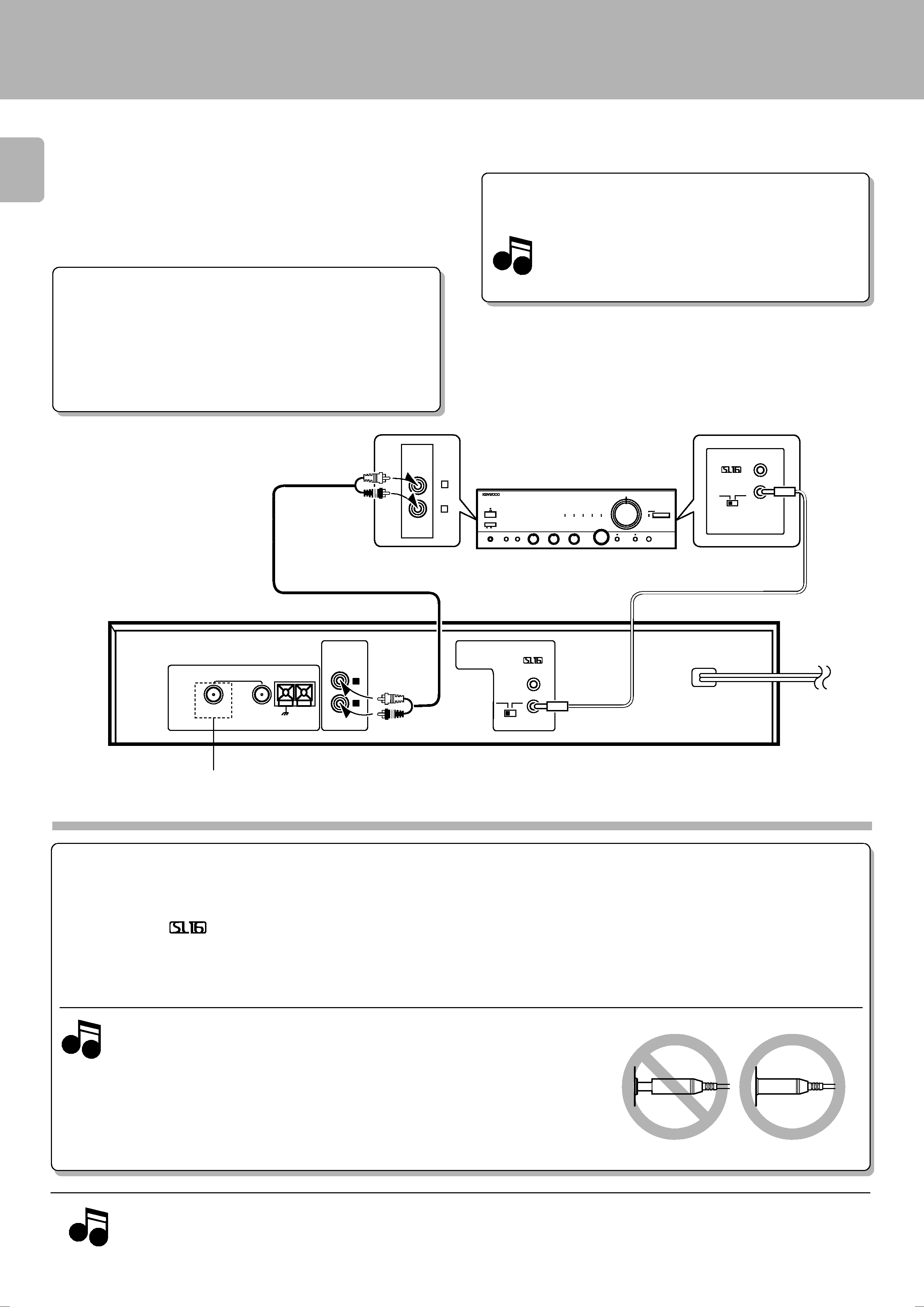
If this tuner is connected to a KENWOOD amplifier with the system control cord, the amplifier
automatically switches the input source to the tuner input when the program of the reserved
information starts, even when you are listening to the input source other than the tuner.
STATION PRESET
This unit features a function which stores the broadcast station you are listening to with easy
operations and allows you to store a name for the station.
It is very convenient to register the desired stations. Also, you can recall the stations with easy
operations.
Contents
Before applying power
................................................................................................................................................................. 2
Before applying power ....................................................................................................................... 2
Safety precautions ............................................................................................................................. 2
Special features ........................................................................................................................................ 3
System connection
................................................................................................................................................................. 4
Controls and indicators
................................................................................................................................................................. 6
Useful functions for broadcast reception
................................................................................................................................................................. 7
Broadcast reception
................................................................................................................................................................. 8
Receiving a broadcast station (other than RDS stations) .......................................................................... 8
RDS (Radio Data System)
................................................................................................................................................................. 9
Storing broadcast stations in memory
............................................................................................................................................................... 10
Receiving a preset station
............................................................................................................................................................... 11
Entering broadcast station names
............................................................................................................................................................... 12
PTY search
............................................................................................................................................................... 13
EON reservation
............................................................................................................................................................... 15
In case of difficulty
............................................................................................................................................................... 16
Specifications
............................................................................................................................................................... 17
Special features
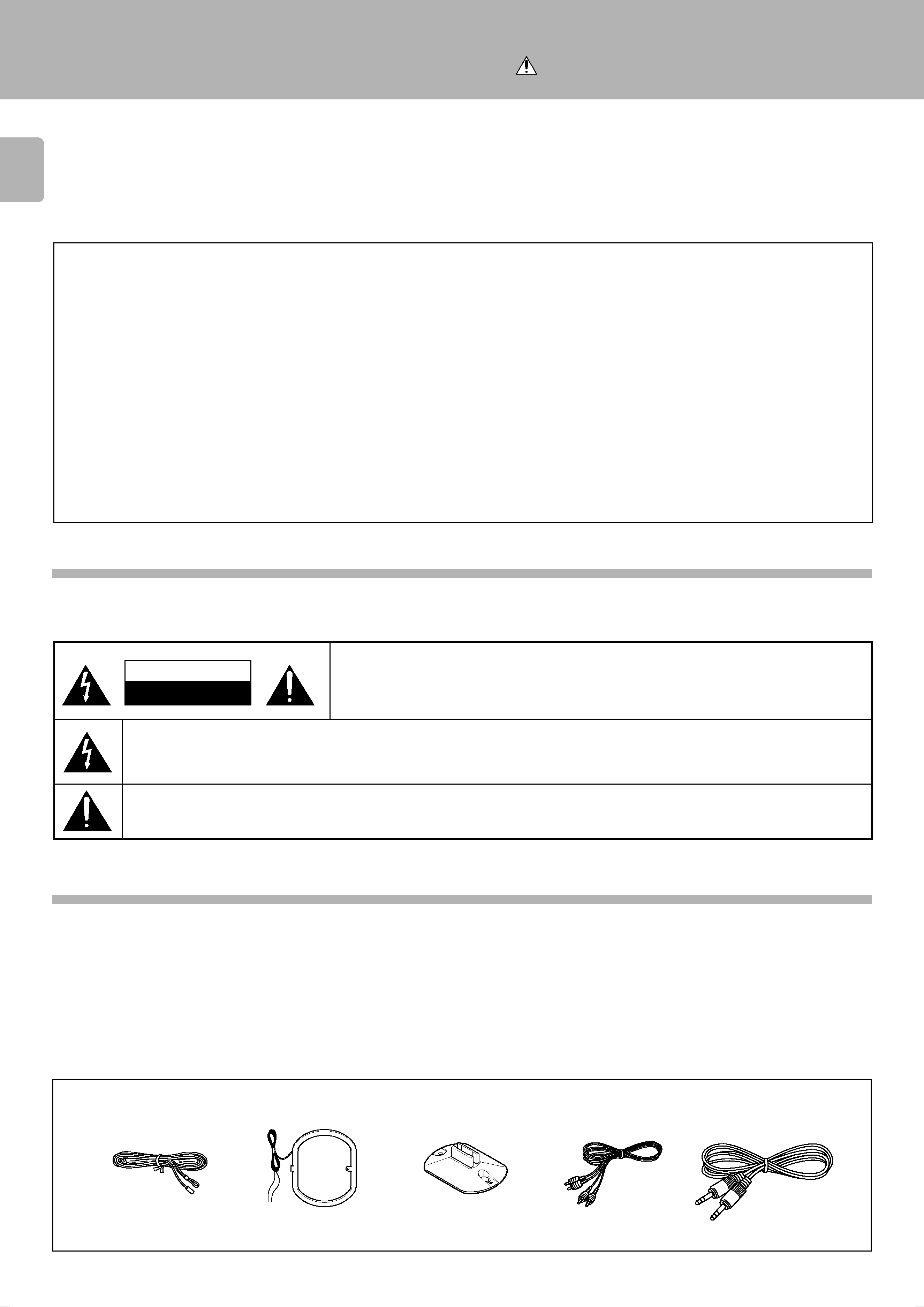
Caution : Read the pages marked
carefully to ensure safe operation.
background image
KTF-3010/KTF-2010 (En)
4
R
L
TUNER
SYSTEM CONTROL
PHONES
A
SPEAKER
B
BASS
TREBLE
BALANCE
INPUT SELECTOR
MUTING
LOUDNESS
ON
OFF
POWER
ON/STANDBY
STEREO INTEGRATED AMPLIFIER
KAF-3010R
MIN
MAX
VOLUME CONTROL
MD
TAPE
TUNER
PHONO
CD
SOURCE DIRECT
thermally reactive advanced instantaneous transistor
TRAIT
|{
|{
LR
ANTENNA
GND
AM
FM
75
B
A
SYSTEM
CONTROL
OUTPUT
R
L
SL16 XS 8
SL16 XS 8
System connection
Connection of the Audio components/Connection of the system control cord
Make connections as shown below.
When connecting the related system components, refer also
to the instruction manuals of the related components.
Do not plug in the power lead until all connections are com-
pleted.
Pre-main amplifier
Audio cord
System control cord
To wall AC
outlet
1.Connect all cords firmly. If connections are loose, you may lose the sound or interconnectable system control operations may not work.
2.When plugging and unplugging connection cord, be sure to first remove the power cord from the AC outlet. Plugging / unplugging
connection cords without removal of the power cord can cause malfunctions or damage to the unit.
Malfunction of microcomputer
If operation is not possible or erroneous display ap-
pears even though all connections have been made
properly, rest the microcomputer referring to "In case
of difficulty".
^
Notes
Notes
KTF-3010 only
Connecting system control cords after connecting a Kenwood audio component system lets you take advantage of convenient system
control operations.
There are two Kenwood system control modes. Make connections according to the groups of terminal symbols shown below.
[SL16] Mode : for
terminals only
[XS8] Mode
: lets you combine
F, f, and terminals
This unit is compatible with both [SL16] and [XS8] modes. It comes from the factory set to the [SL16] mode. To switch to the [XS8] mode,
follow the instructions in "Switching from [SL16] to [XS8]".
1. [SL16] equipment cannot be combined with [XR], [XS], and [XS8] equipment for system
operations. If your equipment consists of this kind of combination, please do not connect
any system control cords. Even without system control cords, normal operations can be
carried out without affecting performance.
2. If your amp or receiver does not have a system control terminal, do not connect any
system control cords to the system control terminals on the other components.
3. Do not connect system control cords to any components other than those specified by
Kenwood. It may cause a malfunction and damage your equipment.
4. Be sure the system control plugs are inserted all the way in to the system control termi-
nals.
Notes
Notes
Caution regarding placement
To maintain proper ventilation, be sure to leave a space around the
unit (from the largest outer dimensions including projections) equal
to, or greater than, shown below.
Left and right panels: 10 cm
Rear panel: 10 cm
No matter to which of the two terminals the con-
nection is made, the use method is the same.
The system control connection
background image
KTF-3010/KTF-2010 (En)
5
The system control operations
Remote Control
Lets you operate this unit with the system remote supplied with the amp or receiver.
Automatic Operation (except [XR] equipment)
Automatically switches the input selector on the amp when you operate one of the tuning keys on this unit.
Automatic EON reception
Even if the input selector on the amp is set to a source other than tuner, the amp will automatically switch to tuner when an EON
broadcast you are waiting for is received. When using equipment connected in the [SL16] mode, the amp will switch back to the
original input source when EON broadcast has finished.
%
Switching from [SL16] to [XS8]
Use the rear panel switch to switch to the system control [XS8] and [SL16] modes. Do this operation
after completing all connections.
÷ Remove the AC power cord plug from the wall outlet before switching modes.
÷ This operation will not affect items stored in the memory.
SL16 XS 8
j
Connection of antenna
AM loop antenna connection
The supplied antenna is for indoor use. Place it as far as possible
from the main system, TV set, speaker cords and power cord,
and set it to a direction which provides the best reception.
Do not plug in the power lead until all connections are
completed.
ANTENNA
GND
FM
75
B
A
AM
ANTENNA
GND
AM
FM
75
B
A
SYSTEM
CONTROL
OUTPUT
R
L
SL16 XS 8
Connection method to each antenna terminal
1 Push lever
2 Insert cord
3 Return lever
FM indoor antenna connection
The accessory antenna is for temporary indoor use only.
For stable signal reception we recommend using an
outdoor antenna. Remove the indoor antenna if you
connect one outdoors.
FM outdoor antenna
connection
Lead the 75
coaxial cable connected to
the FM outdoor antenna into the room and
connect it to the FM 75
terminal.
Use a commercially
available antenna
adaptor.
In certain areas, FM broadcast can be received by connecting the antenna cable to a wall antenna terminal (CATV antenna socket, etc.).
If there is only one antenna, connect it to side A of the
antenna terminal.
The figure shows an example for the KTF-3010

Reviews

There are no reviews of this manual yet.