KENWOOD KTCV500E Service Manual

Cover page of KENWOOD KTCV500E Service Manual

Service Manual for KENWOOD KTCV500E, downloadable as a PDF file.

We also have owner's manual to this model.

Manual details

  • Immediate download after payment.
  • Delivered as a PDF file.
  • The manual has 16 pages
  • File size: 0.78 MB
  • Available language versions: English
  • Different language versions may vary sligthly in file size and page count.

We guarantee that...

  • our manuals are complete,
  • the manual includes circuit diagrams,
  • our manuals are checked with antivirus,
  • We'll issue refund if the manual is damaged, incomplete or unreadable (our refund policy)

Sample pages

Thumbnail of page 1Thumbnail of page 2Thumbnail of page 3Thumbnail of page 4
Thumbnail of page 5Thumbnail of page 6Thumbnail of page 7Thumbnail of page 8
Thumbnail of page 9
background image
TV TUNER
KTC-V500E/N/P
SERVICE MANUAL
© 2002-1 PRINTED IN KOREA
B51-7884-00 (K) 3397
KTC-V500E
4-CHANNEL
DIVERSITY
TV
TUNER
TV
ANTENNA
INPUT
TO
MONITOR
UNIT
The following reference numbers with accessory parts are the same reference numbers
used on EXPLODED VIEW and PARTS LIST.
9
DC1
5
8
6X2
background image
KTC-V500E/N/P
2
ANTENNA SW
TUNER
VIF
SAW
CIRCUIT
DIVERSITY
VIDEO
SW
DEMODULATOR
VIF
VIDEO
SW
MATRIX
RGB SW
DEMODULATOR
VIF
SAW
SIF
DEMODULATOR
FM
MIX
SW
DEMODULATOR
AM
OSC
NOISE
CANCELLER
LPF
SOUND (L/R)
75
6dB
6dB
75
RGB-OUT
VIDEO
8V AVR
SW
14.4V
ACC
AVR
IC401
IC400
Q103
Q101
IC300
IC200
IC301
IC504
IC502
IC202
IC203
IC700
ACC 5V
Q702
8V AVR
Q703
5V AVR
5V AVR
Q705
Q704
A 8V
V 8V
V 5V
A 5V
IC701
DC/DC
+30V
Q701
REGULATOR
POWER SUPPLY
KTC-V500E/N/P (E/K/M)
NTSC
PAL
SECAM
SYNC
DECODER
SDA
SCL
SCL
SDA
OTHERS
L'
: 38.9MHz
: 33.9MHz
I
BG
: 33.4MHz
: 32.9MHz
L'
DK/L
: 40.4MHz
: 32.4MHz
FM/AM
L'
D/K
B/G
I
22.7MHz
21.7MHz
22.2MHz
FM/AM
P. ON
10.7MHz
BLOCK
DIAGRAM
background image
KTC-V500E/N/P
3
COMPONENT DESCRIPTION
ELECTRIC UNIT (X25-928x-xx)
REF.
No.
FUNCTION
OPERATION
IC200
TV VIF/CHROMA
Detects VIF, and processes chroma.
IC202
VIDEO AMPLIFIER
Amplifies G and B signals up to 6dB at 75 ohms.
IC203
VIDEO AMPLIFIER
Amplifies SYNC and R signals up to 6dB at 75 ohms.
IC300
TV VIF/SIF
Detects VIF and SIF (Euro model's one is for diversity).
IC301
AM DETECTION
Detects SIF (AM).
IC400
VIDEO SW
Switches diversity video signal.
IC401
TV DIVERSITY
Switches TV antenna.
IC502
OPERATION AMPLIFIER
LPF & amplifier.
IC504
NOISE CANCELER
Cancels noise.
IC700
AVR
5V local regulator.
IC701
DC/DC REGULATOR
Switches DC/DC voltage.
IC702
AVR
8V local regulator.
IC800
SYSTEM u-COM
Controls functions.
IC801
RESET IC
Resets system u-com.
Q100
IF SW
Switches SAW filter input IF.
Q101
SIF AMPLIFIER
Amplifies SIF.
Q102
IF SW
Switches SAW filter input IF.
Q103
VIF AMPLIFIER
Amplifies VIF.
Q201,202
BUFFER
Creates H-sync pulse.
Q203,204
BUFFER
Buffers video signal.
Q205-207
RGB MUTE
Mutes RGB signals.
Q208-210
RGB BUFFER
Buffers RGB signals.
Q211,212
VIDEO BUFFER
Buffers video signal.
Q300-302
CLOCK SW
Switches clock.
Q303,304
VIDEO BUFFER
Buffers video signal.
Q305
SYNC PIF SW
Switches sync PIF frequency.
Q306,307
S-METER DC AMPLIFIER
Amplifies s-meter DC.
Q308
VIDEO BUFFER
Buffers video signal.
Q309
VIDEO MUTE
Mutes TV video signal.
Q400
VIDEO MODE SW
Switches diversity video mode.
Q401
ADJUST MODE SW
Switches diversity adjustment mode.
Q500,501
AUDIO MUTE
Mutes audio signal.
Q700
Q701 DRIVER
Drives Q701.
Q701
POWER SW
Switches back-up power supply.
Q702
8V AVR
Supplies power to TV front-end and IF circuit.
Q703
8V AVR
Supplies power to IC200.
Q704
5V AVR
Supplies power to TV front-end and IC301.
Q705
5V AVR
Supplies power to video circuit.
Q706
B.U. DETECTION
Detects back-up.
Q800
PANEL/BASS RESET SW
Controls reset for panel and bass.
background image
KTC-V500E/N/P
4
MICROCOMPUTER'S TERMINAL DESCRIPTION
(X25-) IC800 : SYSTEM u-COM
PORT
No.
PORT NAME
I/O
FUNCTION
OPERATING CONDITION
1
DIV
O
Diversity adjustment mode (Test mode).
"H" : Adjustment mode on (Diversity forced off).
2-4
--
-
-
5
DK
O
IF switch (When state of PAL-D).
"H" : DK area.
6
IF
IF switch (Group 3 when state of PAL-I).
"H" : I area.
7
BG
O
O
IF switch (Group 1/2 when state of PAL-B/G).
"H" : BG area.
8
-
-
-
9
VDD
-
5V power supply.
-
-
10
X2
-
Main system clock oscillation (12.28MHz).
-
11
X1
-
Main system clock oscillation (12.28MHz).
-
12
VSS
-
GND.
-
13,14
--
-
-
15
RESET
-
System reset.
"L" : Reset.
16
SC-CON
I
Communication between panel and box.
-
17
MC-REQ
I
Communication between panel and box.
-
18
B.U.
I
Back-up detection.
"H" : B.U. OFF.
"L" : B.U. ON.
19
P.ON
O
Power-on.
"H" : P.ON OFF. "L" : P.ON ON.
20,21
--
-
-
22
REF.CON
O
A/D converter reference voltage.
ADC comparator power supply switch.
23
AVDD
-
A/D converter analogue power supply.
-
24
AVREF 0
-
A/D converter reference voltage.
-
25
SD
I
SD.
-
26
S-METER
I
S-meter.
-
27-32
-
-
33
AVSS
-
GND.
-
34,35
-
-
-
-
-
-
36
AVREF 1
-
Analogue reference voltage.
-
37
FLASH 1
O
Flash 1.
-
38
FLASH 2
O
Flash 2.
-
39
FLASH 3
O
Flash 3.
-
40-43
-
-
-
-
-
-
-
-
-
-
-
-
-
-
-
-
-
-
-
-
44
SC REQ
O
Communication request in panel.
-
45
MC DATA
I
Communication data in panel.
-
46
SC DATA
O
Communication data in panel.
-
47
MC CLK
I
Communication clock in panel.
-
48
-
-
49
L2
O
Video reception switch (Only in France).
"L" : VHF receiving.
"H" : 2,3,4CH receiving.
50
AM/FM
O
AM/FM audio reception switch.
"L" : AM (Only in France).
"H" : FM (Without France).
51,52
-
-
53
TYPE 1
I
Destination switch.
"L" : For in Europe.
"H" : For in Japan.
54-58
-
-
59
PLL-DATA
O
PLL data.
-
60
PLL-CLK
O
PLL clock.
-
61
PLL-ENB
O
PLL enable.
-
62
TV/V MUTE
O
TV tuner mute / Video mute.
"H" : Mute on.
"L" : Mute off.
63-71
-
-
72
VSS
-
GND.
-
73-78
-
-
79
SP MUTE
O
Speaker audio line mute.
"L" : Mute on.
"H" : Mute off.
80
-
-
81,82
VDD
-
Power supply.
-
83-86
-
-
87
TIME
O
Waiting configuration for communication
beginning with machro IC.
"L" : No waiting.
"H" : 3 seconds waiting.
88-93
-
-
94
TEST
-
VPP voltage for flash memory writing.
"L" : Usual operation.
"H" : Flash memory writing .
95-98
-
-
99
SCL
O
IC2 clock.
-
100
SDA
I/O IC2 data.
-
background image
KTC-V500E/N/P
5
ADJUSTMENT
NG
OK
NG
X25 Circuit Adjustment Specification (K : For North American Markets)
Item
A
djustment method / Adjustment value
Conditions
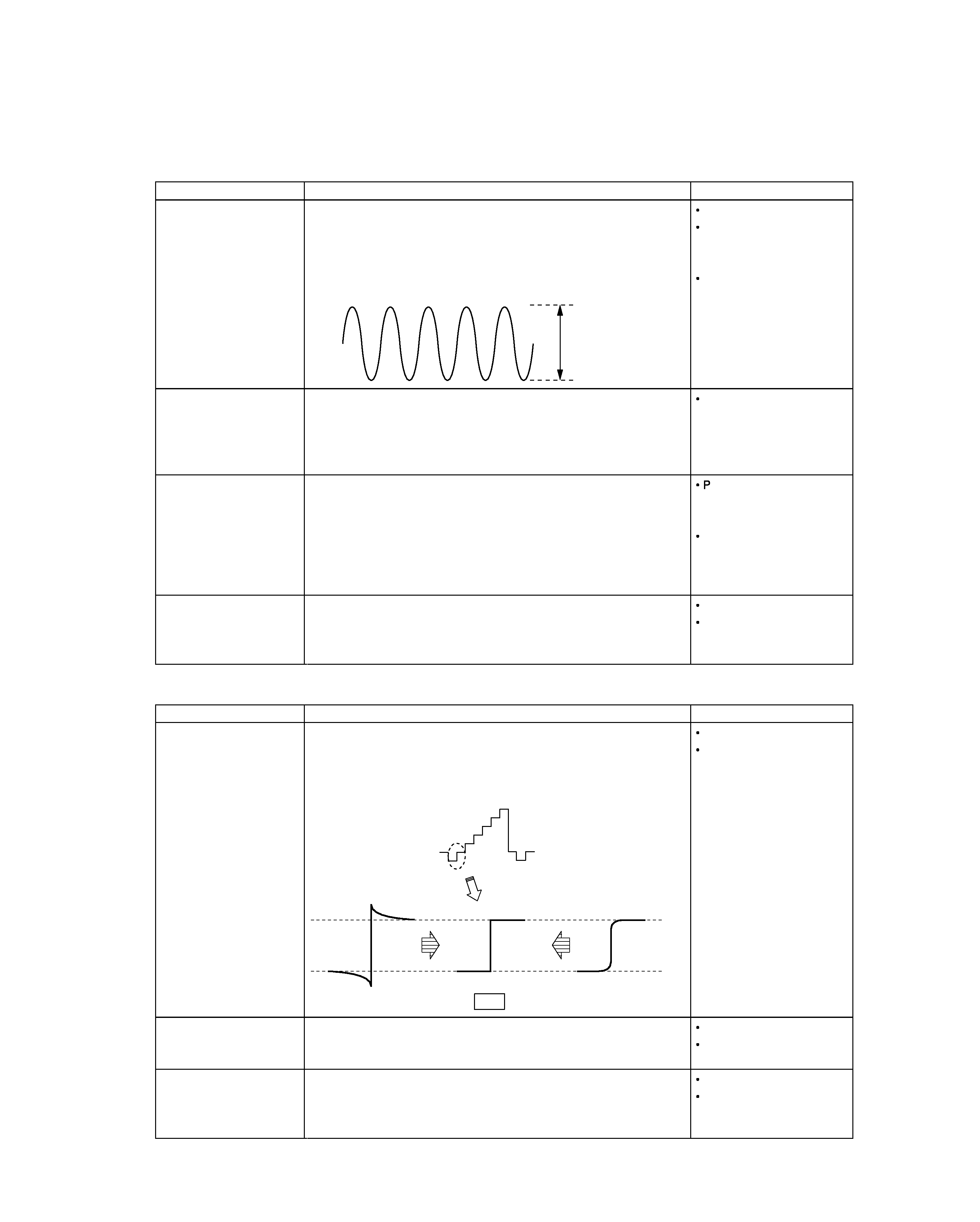
1. Video detection coil
adjustment
L303
1. Turn VR301 [RF-AGC] fully to the right.
2. Apply DC2.0V to TP [IF AGC] (IC300 pin36).
3. Feed fo=45.75MHz, Mod=1kHz, AM60%, Level=100dB
µ into TP [IF]
(A100 pin8).
4. Observe the TP [VIDEO] (IC300 pin8) waveform on an oscilloscope and
adjust L303 for maximum level.
Maximum
No ANT signal
If the waveform is clipped,
slightly increase the DC
voltage.
AC range
2. Audio detection coil
adjustment
L300
1. Turn VR301 [RF-AGC] fully to the right.
2. Feed fo=41.25MHz, No Modulation, Level=94dB
µ into TP [IF] (A100
pin8).
3. Connect a voltmeter to TP [SIF] (both ends of R314) and adjust L300 for
0V
± 0.01V.
No ANT signal
3. S-METER adjustment
VR300
4. RF AGC adjustment
VR301
1. Turn VR301 [RF-AGC] fully to the right.
2. Feed a 30dB
µ11CH color bar RF signal into the ANT input terminal.
3. Audio (P/S ratio -6dB) no modulation.
4. Connect a voltmeter to CN300 and adjust VR300 [SMET] so it reads
3.5V
± 0.05V.
5. Set the RF signal to 70dB
µ and adjust VR301 [RF-AGC] so that the
voltmeter connected to CN300 reads 4.5V
± 0.05V.
ostpone adjusting VR301
to prevent AGC having effect
at 30dB
µ.
Ensure the RF AGC
adjustment is performed
after the S-METER
adjustment.
5. Diversity free run
frequency adjustment
VR400
1. Connect a frequency counter to CN400.
2. Using the remote control unit TV/NAVI button, switch to adjustment
mode.
3. Adjust VR400 [15kHz] so as to obtain 15734
± 10Hz.
No ANT signal
Test mode
X25 Circuit Adjustment Specification (E : For European Markets)
Item
A
djustment method / Adjustment value
Conditions
1. Diversity video detection
coil adjustment
L303
1. Input RF signal 70dB
µ 9CH stair step into the ANT input terminal.
2. Observe the TP [VIDEO] (IC300 pin8) waveform on an oscilloscope and
adjust L303 so that the edges of sync chip and pedestal are horizontal.
PAL B/G
Turn color off.
2. Audio detectioncoil
adjustment
L300
1. Input RF signal 70dB
µ 9CH bar into the ANT input terminal.
2. Connect a voltmeter to TP [SIF] (both ends of R314) and adjust L300 for
0V
± 0.01V.
PAL B/G
P/S ratio 10dB
3. Diversity free run
frequency adjustment
VR400
1. Connect a frequency counter to CN400.
2. Using the remote control unit TV/NAVI button, switch to adjustment
mode.
3. Adjust VR400 [15kHz] so as to obtain 15625
± 10Hz.
No ANT signal
Test mode

Reviews

There are no reviews of this manual yet.