KRF-V7020D/V8020D/VR-307/309/357
4
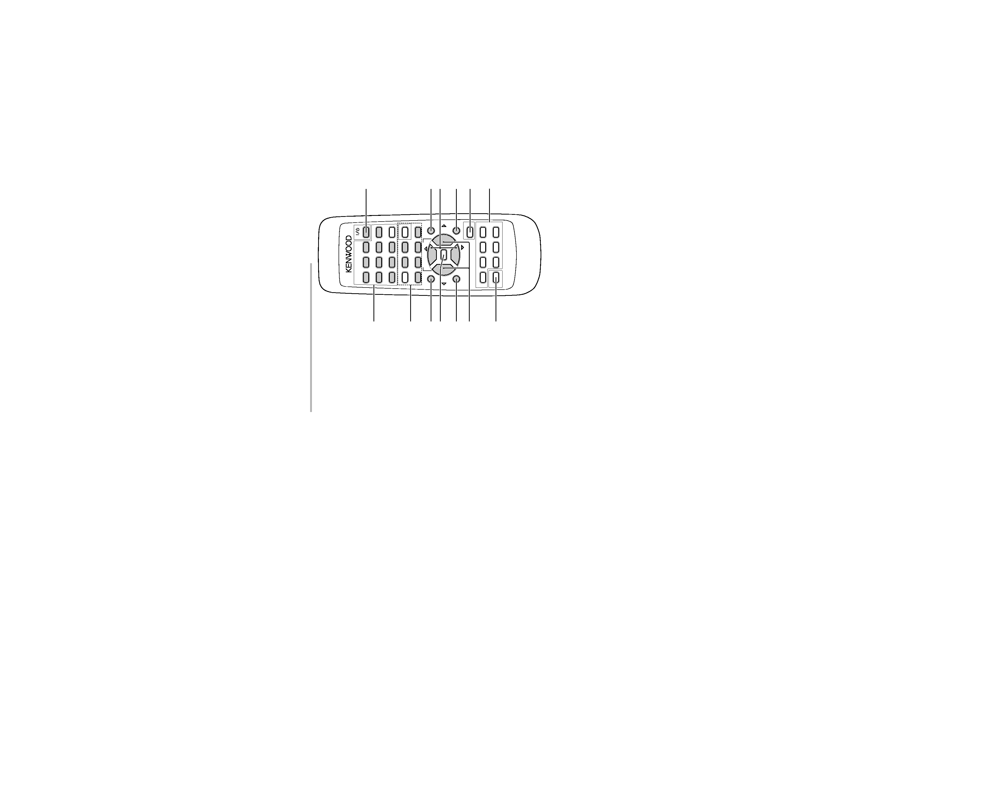
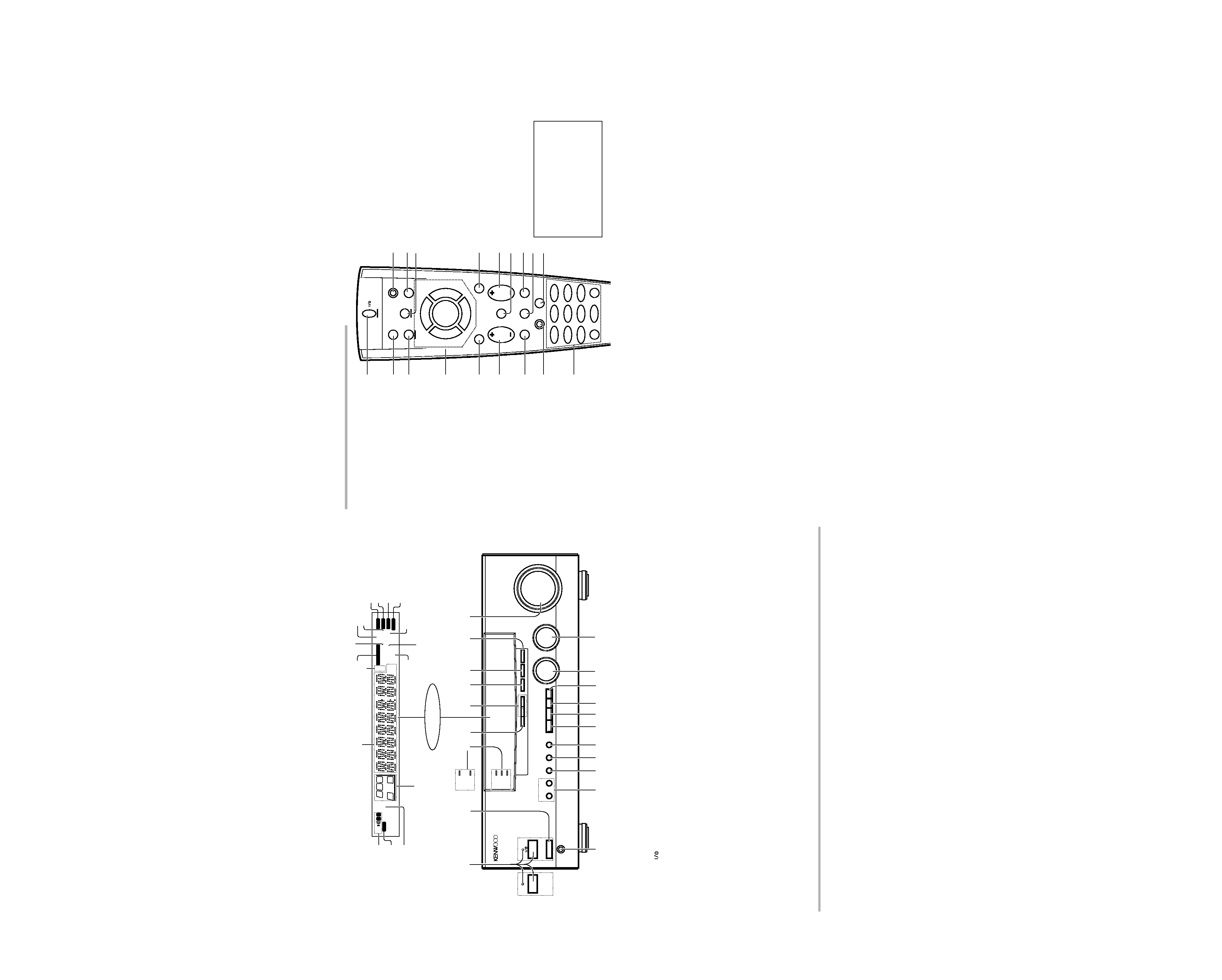
CONTROLS
8 FUNCTION SHIFT key
Use in combination with the numeric keys to
execute alternate commands.
9 Numeric keys
Provide functions identical to those of the
original remote control supplied with the
component you are controlling.
To access the functions printed above the
keys, press within 3 seconds of pressing the
FUNCTION SHIFT key. Function availability
varies for each component.
0 SHIFT key
Use in combination with the AUDIO and
VIDEO keys to change the remote control
mode without changing the input selector or
in combination with the POWER key to turn
on and off components programmed into
the remote control.
! TV selector key
Sets the remote control to operate a TV or
cable box. This key does not change the
input selector on the receiver.
@ AUDIO selector key
Selects the audio inputs and sets the re-
mote control to operate the respective
KENWOOD audio component.
If you connect audio components from
KENWOOD and other makers to the MD/
TAPE or CD jacks, you can set the remote
control to operate these components by
registering the appropriate setup code at
the respective input.
# GUIDE key
Use to activate the OSD menu functions of
registered components.
$ VOLUME key
Use to adjust the receiver volume.
% MUTE key
Use to temporarily mute the sound.
^ SOUND key
Use to adjust the sound quality and ambi-
ence effects.
& LISTEN MODE key
Use to select the listening mode.
* SETUP key
Use to select the surround sound settings.
1 POWER key
Use to turn the receiver on and off.
Use in combination with the input selector
(AUDIO, VIDEO, or TV) keys and SHIFT key
to turn various components on and off.
2 MACRO key
Use in combination with the AUDIO, VIDEO,
or TV keys to execute a series of commands
automatically (MACRO PLAY).
3 VIDEO selector key
Selects the video inputs and sets the remote
control to operate the component regis-
tered at the respective input.
4 Multi control keys
Use to operate the selected component.
5 REC key
Use to operate the selected component.
6 TUNING/SKIP key
Use during the setup procedure to specify
various settings. Use to operate the tuner or
selected component.
7 SUBWOOFER key
Use in combination with the VOLUME +/
keys to adjust the volume of the subwoofer.
There are some cases in which keys (or
knobs) that have the same function on
the receiver and on the remote control
have different names. In the instruc-
tions of this manual, if the names of
corresponding keys (or knobs) on the
receiver and remote control are differ-
ent, the name of the remote control key
is indicated in parentheses.
AUDIO
SHIFT
MACRO
TV
VIDEO
GUIDE
REC
MUTE
VOLUME
TUNING/SKIP
THEME
FAV
MENU
FUNCTION
SHIFT
SETUP
INFO
ALT AUD
TV/SAT/VID
REPEAT
RANDOM
+100
DISPLAY
ENT
+10
LISTEN
MODE
SOUND
SUBWOOFER
23
1
56
4
89
7
0
1
2
3
7
8
9
4
5
6
0
!
#
^
*
&
%
@
$
8
7
4¢
6
BAND
P. CALL
P. CALL
POWER
Remote control unit (RC-R0608 / R0508)
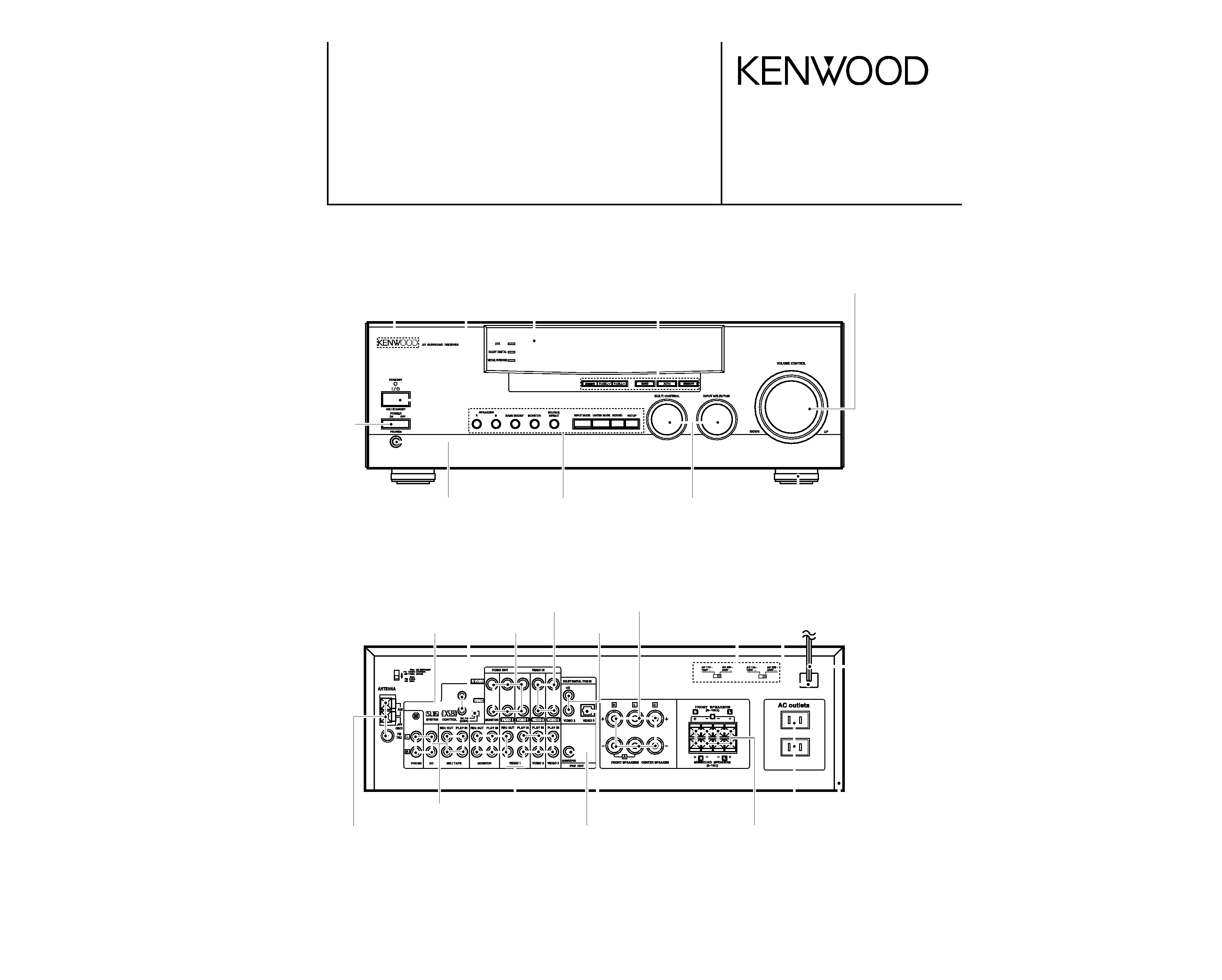
A
SPEAKERS
B
BASS BOOST
MONITOR
SOURCE
DIRECT
INPUT MODE LISTEN MODE SOUND
SETUP
MULTI CONTROL
INPUT SELECTOR
VOLUME CONTROL
DTS
DOLBY DIGITAL
VIRTUAL SURROUND
DOLBY DIGITAL
VIRTUAL SURROUND
DOWN
UP
STANDBY
AV SURROUND RECEIVER
ON / STANDBY
PHONES
- ON
OFF
POWER
POWER
STANDBY
ON / STANDBY
DIMMER
P.CALL
P.CALL
BAND
AUTO
MEMORY
FM
AM
kHz
MHz
3 STEREO
B
S.DIRECT
A
SP
MUTE
DOWNMIX
MONITOR
PRO LOGIC
TUNED
MEMO.
AUTO
ST.
AUTO SOUND
S
SW
C
RS
R
LS
L
LFE
DIGITAL
CLIP
2
8
3 4
6 7
5
9
)
(
%
$
#
@
!
0
^ &*
1
Display
Speaker selection indicators
Input channel indicators
Output channel indicators
AUTO SOUND indicator
Band indicators
AUTO indicator
MEMO. indicator
ST. indicator
TUNED indicator
3 STEREO indicator
STEREO indicator
1 POWER key
(For U.S.A. and Canada)
Use to turn the power ON/OFF.
STANDBY indicator
1 ON/STANDBY (
) key
(Except for U.S.A. and Canada)
Use to switch the power ON/STANDBY
when the POWER is turned ON.
STANDBY indicator
2 POWER key
(Except for U.S.A. and Canada)
Use to turn the main power ON/OFF.
3 Surround indicators
÷ DTS indicator
Lights when the receiver is in the DTS
mode.
(For VR-309, KRF-V8020D)
÷ DOLBY DIGITAL indicator
Lights when the receiver is in the Dolby
Digital mode.
÷ VIRTUAL SURROUND indicator
Lights when the receiver is in the Virtual
Surround mode.
4 DIMMER key
Use to adjust the brightness of the display.
Use to select the REC MODE.
5 P.CALL keys
Use to call up previously registered radio
stations.
6 BAND key
Use to select the broadcast band.
7 AUTO key
Use to select the auto tuning mode.
8 MEMORY key
Use to store radio stations in the preset
memory.
9 VOLUME CONTROL knob
0 PHONES jack
Use for headphone listening.
! SPEAKERS A/B keys
Use to turn the speakers ON/OFF.
@ BASS BOOST key
Use to select the maximum adjustment
setting for the low frequency range.
About the STANDBY indicator
This unit has a STANDBY indicator. When the STANDBY indicator is lit, the unit consumes a small amount of power to preserve the memory. This is called
STANDBY mode. This mode also lets you turn the power ON using the remote control.
Frequency display,
Input display,
Preset channel display,
Surround mode display
Speaker indicator
CLIP indicator
PRO LOGIC
indicator
DIGITAL indicator
S.DIRECT indicator
MONITOR indicator
DOWNMIX indicator
# MONITOR key
$ SOURCE DIRECT key
% INPUT MODE key
Use to switch between the digital and analog
inputs.
^ LISTEN MODE key
Use to select the listening mode.
& SOUND key
Use to adjust the sound quality and amb
ence effects.
* SETUP key
Use to select the surround sound settings
( MULTI CONTROL knob
Used to make a variety of settings.
) INPUT SELECTOR knob
Use to select the input sources.
For U.S.A.
and Canada
MUTE indicator
For VR-307, VR-357
KRF-V7020D