KENWOOD KRC2902G Service Manual

Cover page of KENWOOD KRC2902G Service Manual

Service Manual for KENWOOD KRC2902G, downloadable as a PDF file.

Manual details

  • Immediate download after payment.
  • Delivered as a PDF file.
  • The manual has 17 pages
  • File size: 0.93 MB
  • Available language versions: English
  • Different language versions may vary sligthly in file size and page count.

We guarantee that...

  • our manuals are complete,
  • the manual includes circuit diagrams,
  • our manuals are checked with antivirus,
  • We'll issue refund if the manual is damaged, incomplete or unreadable (our refund policy)

Sample pages

Thumbnail of page 1Thumbnail of page 2Thumbnail of page 3Thumbnail of page 4
Thumbnail of page 5Thumbnail of page 6Thumbnail of page 7Thumbnail of page 8
Thumbnail of page 9
background image
© 2002-1 PRINTED IN JAPAN
B51-7882-00 (N) 1089
CASSETTE RECEIVER
KRC-2902YA/G
SERVICE MANUAL
45Wx4
HIGH POWER
KRC-2902
LOUD
PWR
OFF
AME
AUTO
CLK
SRC
AUD
T. CALL
MENU
WIDE BAND
REW
P R
FF
OG
Lever
(D10-3031-04)x2
Plastic cabinet assy
(A02-1486-13)
Mounting hardware assy
(J21-9491-13)
DC cord
(E30-4790-05)
Antenna adaptor
(T90-0523-05)
Escutcheon
(B07-2124-02)
Knob (ATT)
(K25-1388-03)
Cassette lid
(A53-1638-13)
Panel assy
(A64-2520-02)
background image
KRC-2902Y
A/G
2
BLOCK
DIAGRAM
IC1
KEY
PAN 5V
MUTE
B.U. DET.
B.U.
ACC
POWER IC
EQ. AMP.
CH ISO AMP
NC/MPX/
E-VOL.
FRONT Lch
FRONT Rch
REAR Lch
REAR Rch
J2
LCD DRIVER
LCD
MAIN
TAPE MECHA.
IC5
IC2
IC4, Q151
IC3,Q150
SP OUT
PAN IN SW
ACC DET.
P-CONT.
J2
IC1
FM+B
Q200,201
AM+B
Q202,203
AM BPF
FM BPF
Q320
Q50
Q350-353
Q53
SW 5V
Q54-57
COM+B
Q58-61
ILLUMI.
B.U. 5V
Q51,52
SYSTEM u-COM
RST SW
Q301
MOTOR SW
RST
Q260,261
ED1
Q1
FM ANT
AM ANT
RF GND
FM+B
AM+B
OSC GND
OSC GND
OSC GND
VT
PLL +B
IFC OUT
SDA
SCL
DIG GND
IF1+B
IF1 GND
S-METER
IF2 GND
SD
FM+B
SW5V
ACC DET
B.U. DET
SCL
MUTE
SDA
P CON
P
ANEL
HOLD
L
CLK
L
D
A
T
A
S
L
D
A
T
A
L
FWD/REV
M
OTO
R
Rch
COM
Lch
MP IN
AM
MPX
OUT RR
OUT LR
OUT RF
LEVEL
SCL
SDA
OUT LF
STBY
MUTE
Rch
Lch
T-MUTE
FWD
REV
B.U.5V
B.U.
8V
B.U.
S
MUTE
4
6
5
B.U.5V
AM+B
VDD 5V
P
A
CK
IN
L
RES
ANT CON
BEEP
SVR
AMP. STBY
SVR
AC GND (BEEP)
Rch
Lch
8V
RF GND
OSC GND
IF2 +B
AUDIO OUT
8V
S-METER
SD
PLL CLK
PLL DATA
PLAY
HEAD
R
L
55.6mV
B.U.5V
SW5V
8V
B.U.5V
AM: 170mV
FM: 400mV
TAPE
PACK IN
(FF/REW)
AMP. MUTE
FF/REW
B.U.5V
ILLUMI.
(X16- )
(X14- )
M
A1
5V
D200
P-CONT.
/ANT-CONT.
background image
KRC-2902YA/G
3
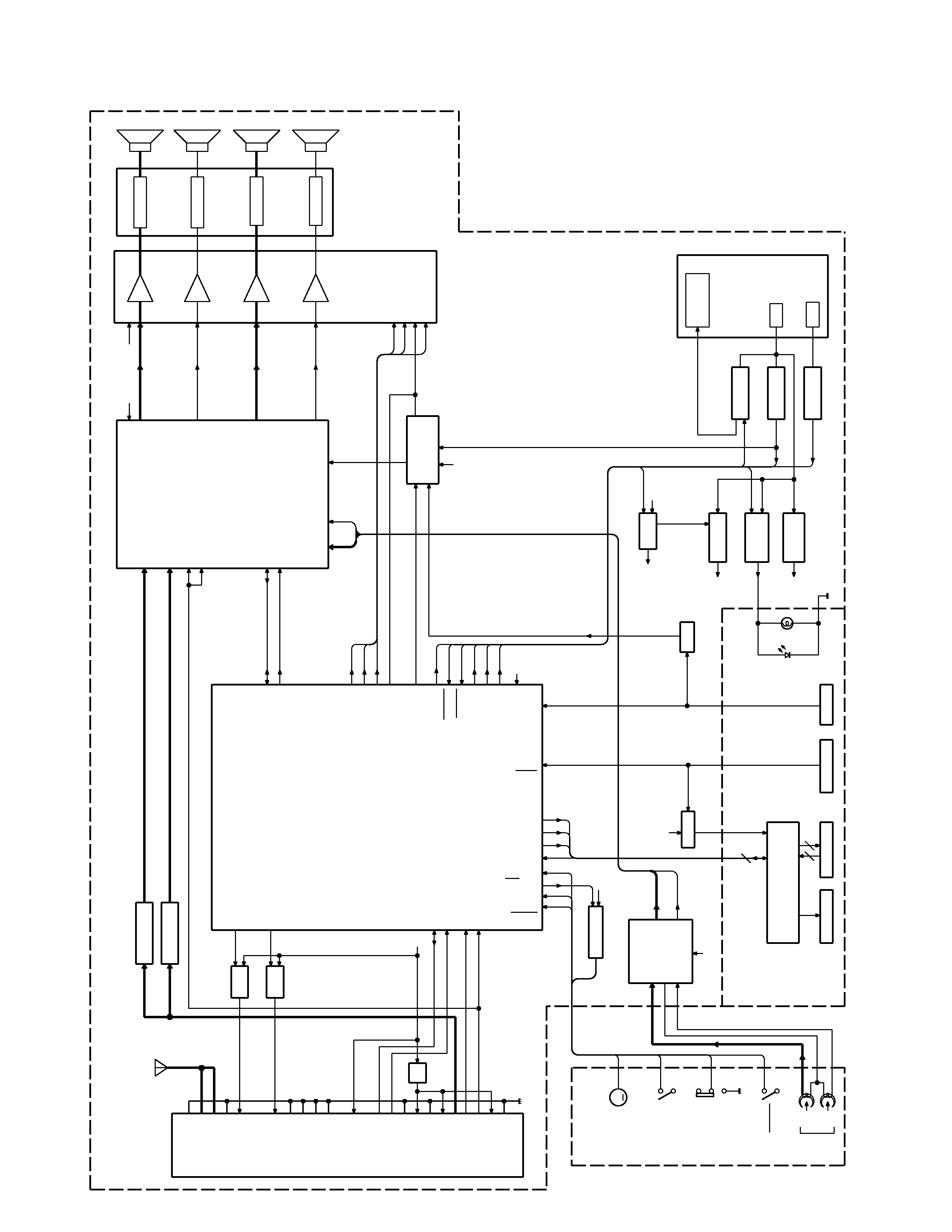
q SYNTHESIZER UNIT (X14-6872-73)
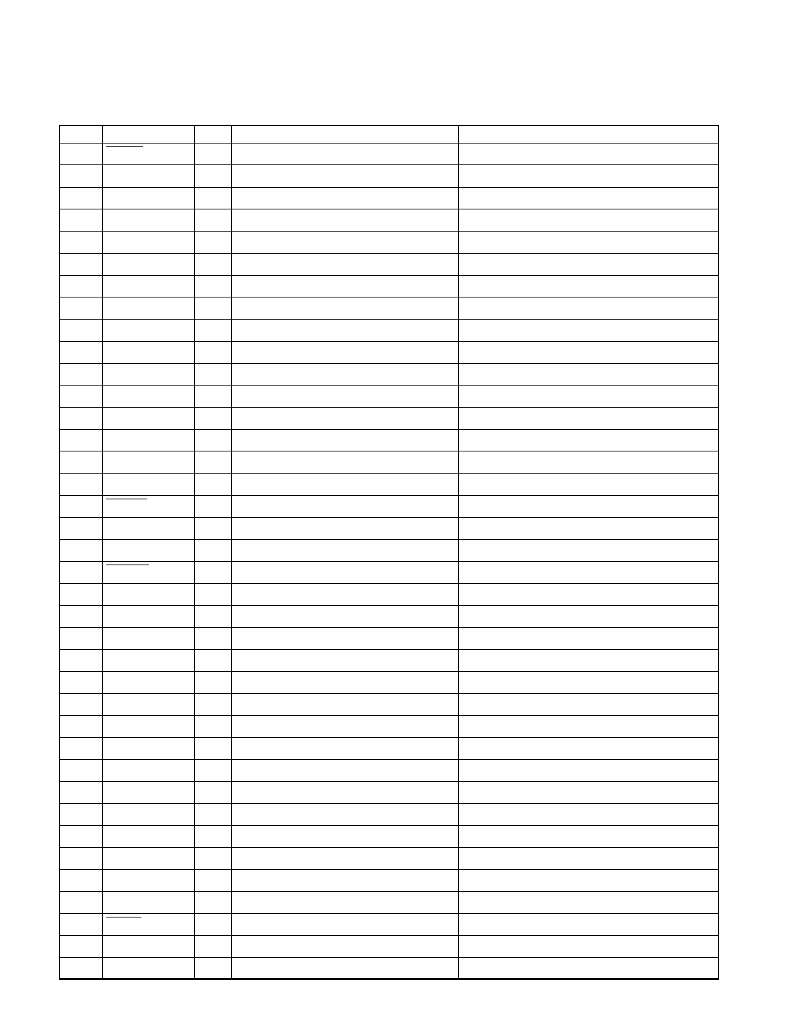
COMPONENTS DESCRIPTION
Ref.No.
Function
Operation
IC1
SYSTEM
µ-COM
Controls the unit.
IC2
E -VOLUME
Controls the volume and selects source.
IC3
M UTE LOGIC
Controls the mute output.
IC4
POWER AMPLIFIER
For the speaker output.
IC5
EQUALIZER AMPLIFIER
For the cassette tape's signal.
IC6
RESET
Resets the power.
Q49
A CC DETECTION SW
Outputs "H" during the ACC off.
Q50
BACK-UP DETECTION SW
Outputs "H" when the back-up voltage is under 9.2V.
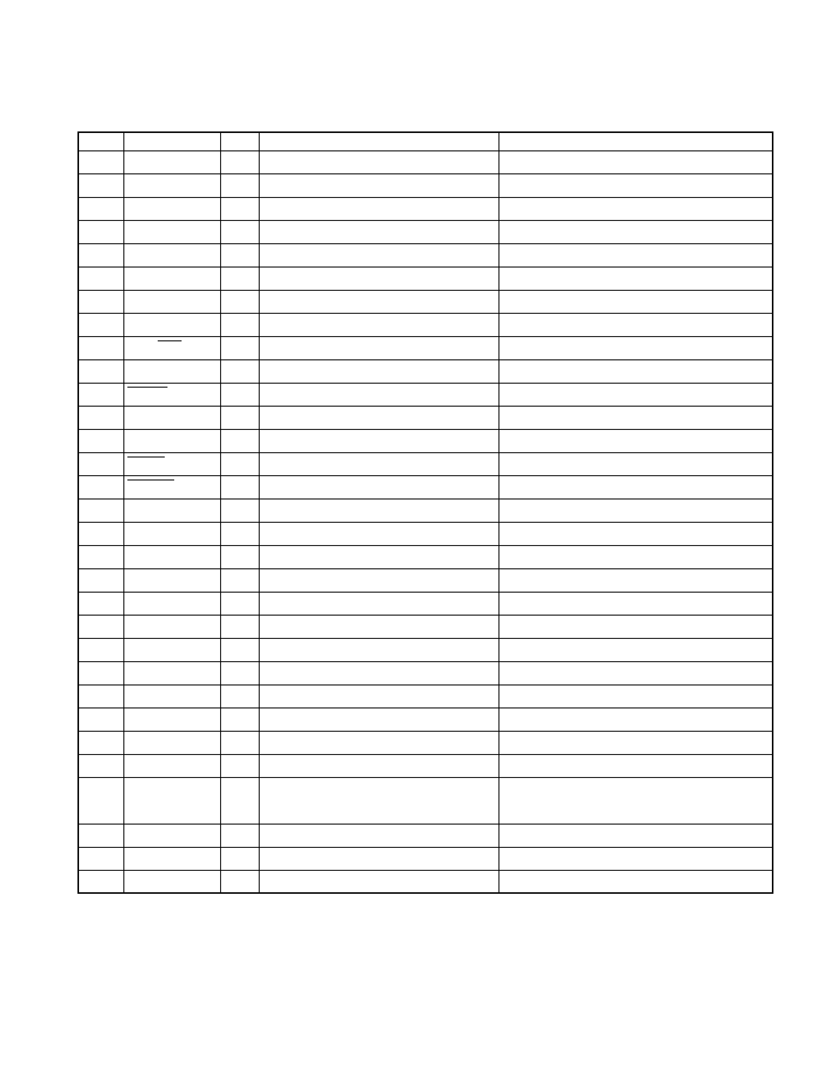
Q51,52
BACK-UP 5V DRIVER
Works when back-up current exists.
Q53
P.ON 5V SW
Works during the power on.
Q54,55
8V SW
Works during the power on.
Q56,57
8V DRIVER
Works during the power on.
Q58,59
ILLUMI +B SW
Works during the power on.
Q60,61
ILLUMI +B DRIVER
Works during the power on.
Q150
E-VOL MUTE SW
Works when the back-up current is detected or the changer mute works or system
µ-com mute works.
Q151
SVR FORCED DISCHARGE SW Works when the amplifier mute works.
Q201
FM +B SW
Works during FM mode.
Q203
AM +B SW
Works during AM mode.
Q260
MOTOR +B SW
Works during the tape mode.
Q261
MOTOR +B DRIVER
Works when Q206 works.
Q301
CD-CH RESET SW
Works when the power is reset and the reset SW works.
Q320
PANEL 5V SW
Works when the back-up current exists and the panel is attached on the unit.
Q350
P.CON DRIVER SW
Does not work during the power off and the ALL OFF.
Q351
P.CON PROTECTION SW
Works when the P.CON is short-circuited on the GND.
Q352
P.CON PROTECTION INHIBIT SW Inhibits the protection SW in a moment during the P.CON on.
Q353
P.CON DRIVER SW
Does not work during the power off and the ALL OFF.
background image
KRC-2902YA/G
4
q
µ-COM (IC1 : X14-)
Pin No.
Pin name
I/O
Description
Processing Operation
1
PANEL
I
Panel detection.
"L" : Panel exists.
2
L CE
O
LCD driver chip enable.
-
3
L RES
O
LCD driver reset.
-
4
AVSS
-
GND.
-
5
R DATA
I
RDS data.
-
6
R QUAL
I
RDS receiving.
-
7
AVREF 1
-
Reference voltage.
-
8
I C2 SEL 1
I
Selector.
"L" : Normally.
9
I C2 SEL 0
I
Selector.
"L" : Normally.
10
-
-
-
-
11
L DATA L
I
LCD driver communication data.
-
12
L DATA S
O
LCD driver communication data.
-
13
L CLK
O
LCD driver communication clock.
-
14,15
-
-
-
-
16
DATA C
I
Changer communication data.
-
17
DATA H
O
Changer communication data.
-
18
CH CLK
I
Changer communication clock.
-
19-26
-
-
-
-
27
MOTOR
O
Cassette tape motor SW.
-
28
FF/REW
I
Cassette tape FF/REW detection.
"L" : FF or REW works.
29-31
-
-
-
-
32
SD
I
Signal detection.
"H":Signal exists.
"L" : Signal does not exist.
33
VSS 1
-
GND.
-
34
-
-
-
-
35
PLL CLK
O
Front-end communication clock.
-
36
PLL DATA
I/O
Front-end communication data.
-
37
AM +A
O
AM power supply SW.
-
38
FM +B
O
FM power supply SW.
-
39
IC2 DATA
I/O
E-volume communication data.
-
40
IC2 CLK
O
E-volume communication clock.
-
41
AFC
O
FM noise detection /Time constant SW.
-
42
MUTE
O
Mute control.
-
43
AMP MUTE
O
Power amplifier mute.
-
44
-
-
-
-
45
CH CNT
O
Changer control.
-
46
REQ H
O
Changer request.
-
47
-
-
-
-
48
SVR
O
SVR control.
-
MICROCOMPUTER'S TERMINAL DESCRIPTION
background image
KRC-2902YA/G
5
Pin No.
Pin name
I/O
Description
Processing Operation
49
AMP STBY
O
Power amplifier stand-by.
-
50
BEEP
O
Buzzer signal output.
-
51,52
-
-
-
-
53
P.CONT
O
Power control SW.
-
54
ACC DET
I
ACC detection.
-
55
B.U.DET
I
Back-up detection.
-
56
P.ON
O
Power SW.
-
57
ILLUMI
O
Illumination SW.
-
58
FWD/REV
I
Cassette mechanism FWD/REV detection.
-
59
-
-
-
-
60
RESET
I
System reset signal input.
-
61
SEL 1
I
Destination SW.
-
62
R CLK
I
RDS clock.
-
63
REQ C
I
Changer request.
-
64
PACK IN
I
Cassette tape pack-in detection.
-
65
KEY-REQ
I
Key signal input detection.
-
66
SEL 0
I
Destination SW.
-
67
VSS 0
-
GND.
-
68
VDD 1
-
5V power supply.
-
69
X2
-
Main system clock.
-
70
X1
I
Main system clock.
-
71
IC
-
GND.
-
72
-
-
-
-
73
XT1
-
5V power supply.
-
74
VDD 0
-
5V power supply.
-
75
AVREF 0
I
A/D converter reference voltage.
-
76
S METER
I
S-meter detection.
"H" : S-meter exists.
"L" : S-meter does not exist.
77
PHONE
I
-
Navigation mute : 2.5V or more.
Telephone mute : 1V or less.
78
NOISE
I
FM noise detection.
-
79
AV CONT
O
A/D converter reference voltage.
-
80
-
-
-
-
MICROCOMPUTER'S TERMINAL DESCRIPTION

Reviews

There are no reviews of this manual yet.