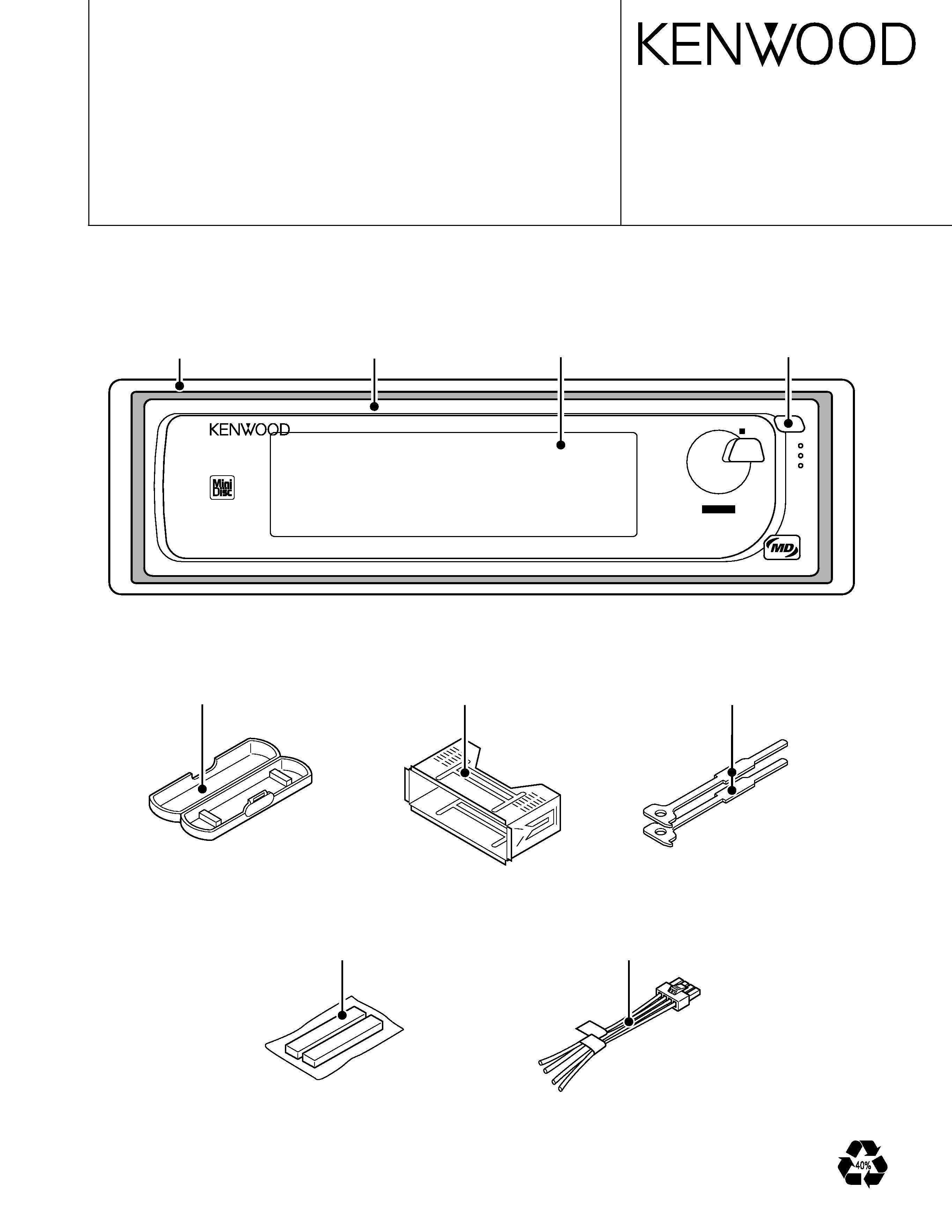
KMD-D401
5
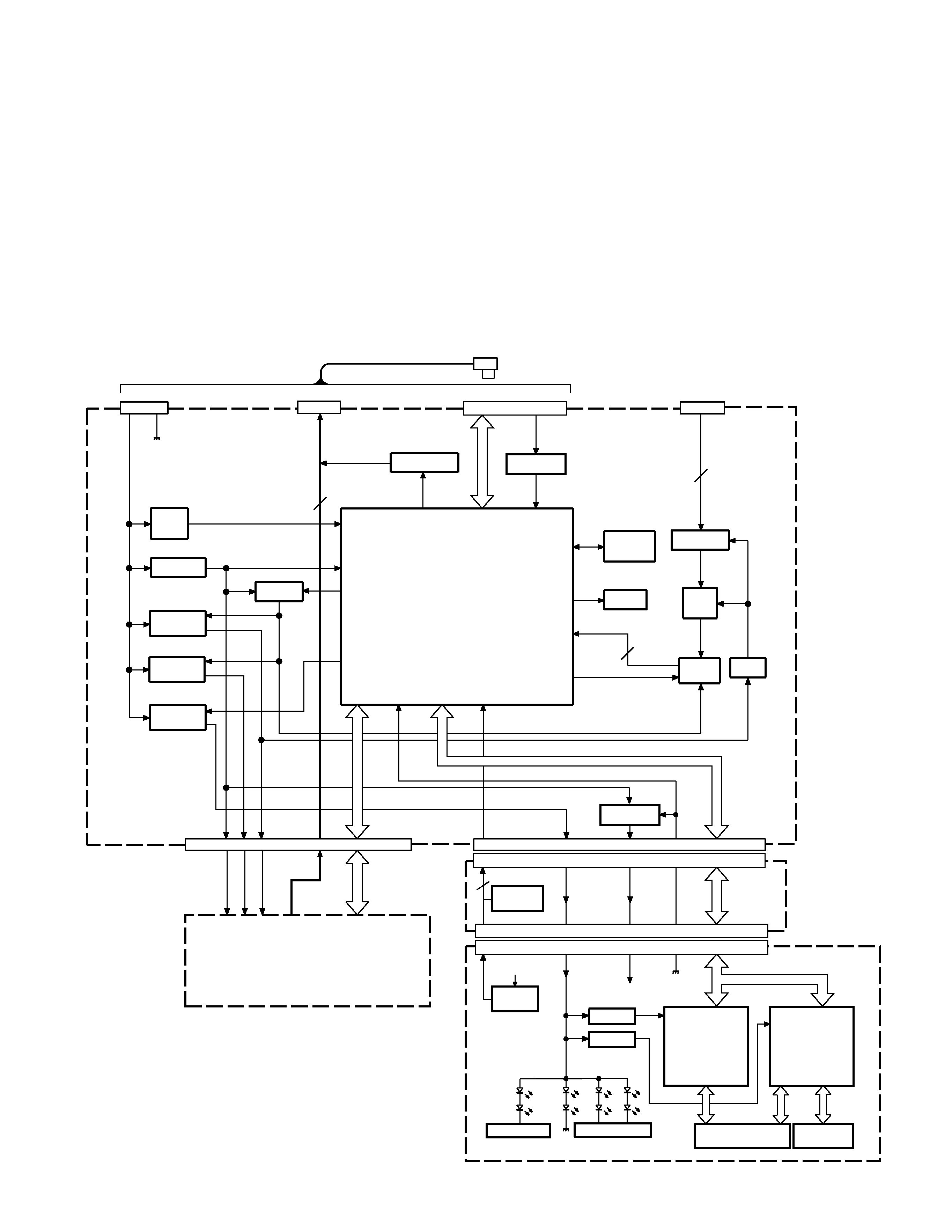
MICROCOMPUTER'S DESCRIPTION
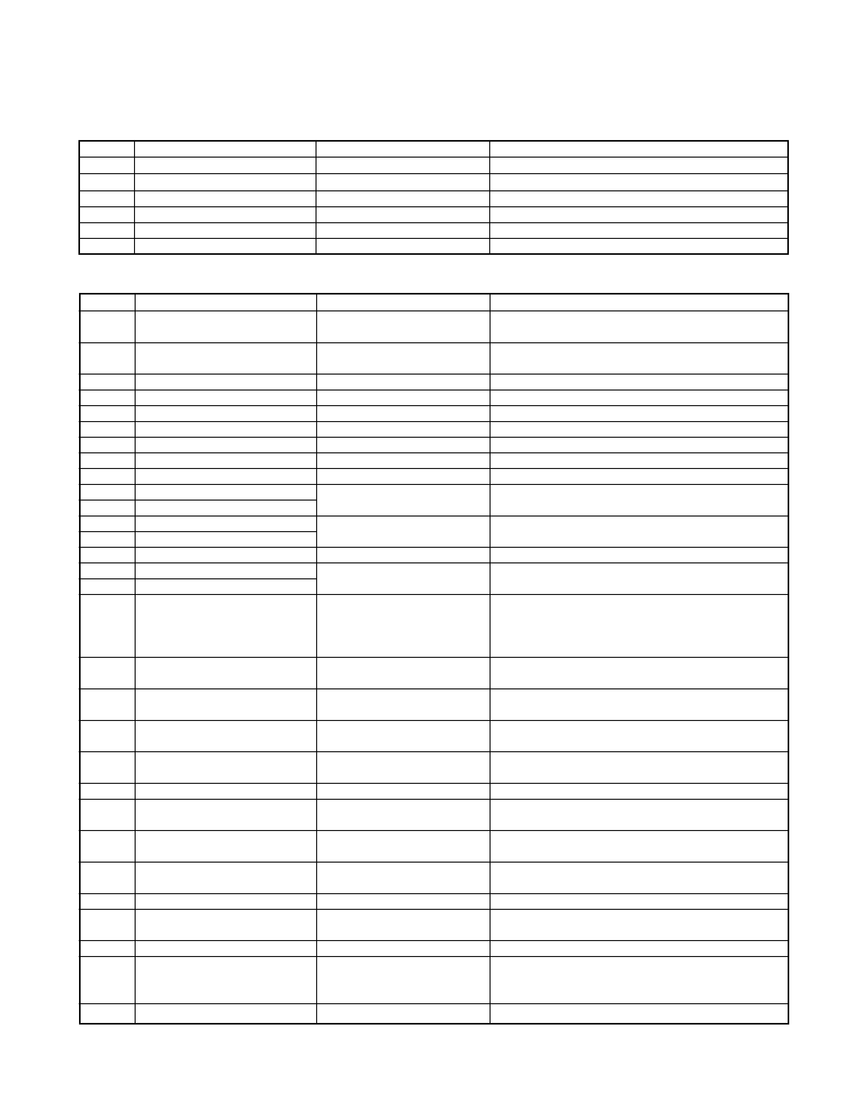
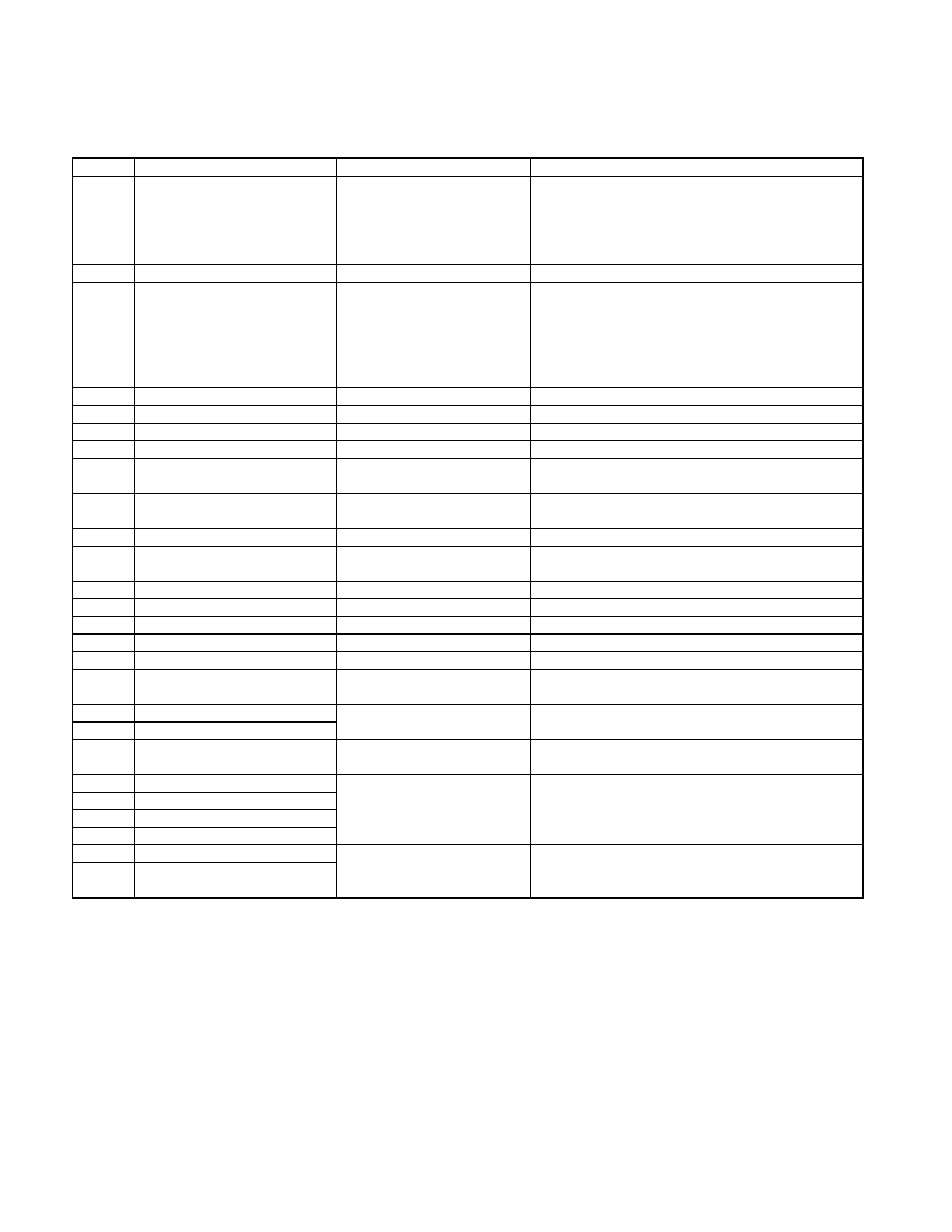
IC3 (ELECTRIC UNIT: X25-8912-71)
q Terminal Description
Pin No. Pin Name
I/O
Description
Processing Operation
1
M0
O
M1,M2,M3 common control output
All Stop : (M0,M1,M2,M3)=("Lo","Lo","Lo","Lo")
Load
: (M0,M1,M2,M3)=("Lo","Hi","Lo","Lo")
2
M3
O
MD mechanism elevator control output
Eject
: (M0,M1,M2,M3)=("Hi","Lo","Hi","Hi")
Pressure : (M0,M1,M2,M3)=("Lo","Lo","Hi","Lo")
3
M2
O
MD mechanism roller control output
Leaving : (M0,M1,M2,M3)=("Hi","Hi","Lo","Hi")
Rise
: (M0,M1,M2,M3)=("Lo","Lo","Lo","Hi")
4
M1
O
MD mechanism Load/Eject control output
Descent : (M0,M1,M2,M3)=("Hi","Hi","Hi","Lo")
Brake
: (M0,M1,M2,M3)=("Hi","Hi","Hi","Hi")
5
SS3 SW
I
Storage shelf 3(Bottom) disc detection input
"Lo": MD detect
6
SS2 SW
I
Storage shelf 2(Middle) disc detection input
"Lo": MD detect
7
SS1 SW
I
Storage shelf 1(Top) disc detection input
"Lo": MD detect
8
LPSCO
O
A/D converter reference power supply control
9
VDD
-
Positive power supply connection terminal
Connected to BU 5V lines.
10
X2
-
Main clock resonator connection terminal
11
X1
I
Main clock resonator connection terminal
12
VSS
-
Ground connection terminal
Connected to ground lines.
13
XT2
-
Sub clock resonator connection terminal
Not used(N.C.)
14
XT1
I
Sub clock resonator connection terminal
Not used(connected to ground lines)
15
RESET
I
Reset input terminal
"Lo": Reset
16
EJECT
I
Eject SW input
"Lo": Eject SW pressed
17
MS SW
I
Disc eject completion detection input
"Hi": Disc eject completed
18
COMM SW
I
5-line communication previous/new switch input
"Hi": New type, "Lo": Previous type
19
FLIP SW
I
Panel tilting detection input
"Hi": Panel tilted or detached, "Lo": Panel closed
20
FS SW
I
Disc-in detection switch input
"Lo": MD detect
21
OS SW
I
Disc insertion orientation switch input
"Lo": Normally insertion
22
CHCON
I
Changer control input from H/U
"Lo": Operation mode
23
AVDD
-
A/D converter analogue power supply connection Connected to BU 5V lines.
terminal
24
AVREF0
-
A/D converter reference voltage input terminal
Connected to SW 5V lines.
25
I
Not used(connected to ground lines)
26
BPF IN
I
Level detection input from BPF IC out
27
MLPS
I
MD mechanism LPS input
Reference voltage 0.25V at SS1, 1.43V at SS2,
2.59V at SS3 4.61V at play position 3.73V at play
position under limit
28
I
Not used(connected to ground lines)
29
PS SW
I
Pack-in completion detection switch input
"Lo": Pack-in completed
30
LS SW
I
Loading completion detection switch input
"Lo": Loading completed
31
CS SW
I
Change lever position detection switch input
"Lo": Roller leaving
32
I
Not used(connected to ground lines)
33
AVSS
-
A/D, D/A converter ground connection terminal
Connected to ground lines.
34
A MUTE
O
Audio mute control output
"Hi": Audio mute
35
CH MUTE
O
Audio mute request output to H/U
"Lo": Audio mute request
36
AVREF1
-
D/A converter reference voltage input terminal
Connected to BU 5V lines.
37
P KEY
I
Key data input from LCD driver IC
38
L DATA
O
Data output to LCD driver IC
39
L CLK
O
Clock output to LCD driver IC
40
DATAH
I
Data input from H/U
41
DATAC
O
Data output to H/U
42
HCLK
I/O Clock input/output with H/U
New type: Input, Previous type: Output
43
REQC
O
Communication request to H/U
"Lo": Communication request
44
PON
O
P ON control output
"Lo": Peripheral circuits are working.
45
M SDA
I/O I2C-Bus data input/output terminal
46
NC
O
Not used(N.C.)
47
M SCL
O
I2C-BUS clock output