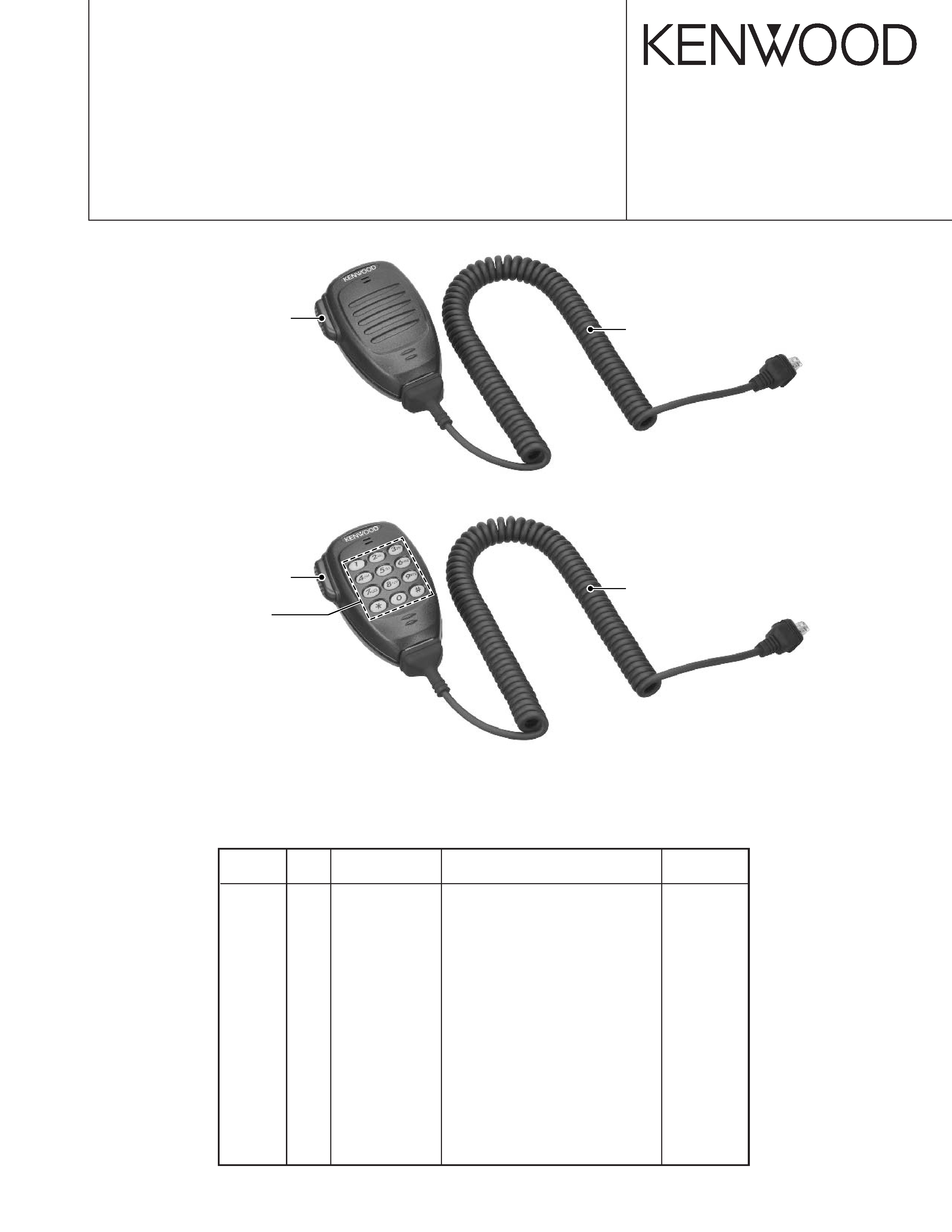
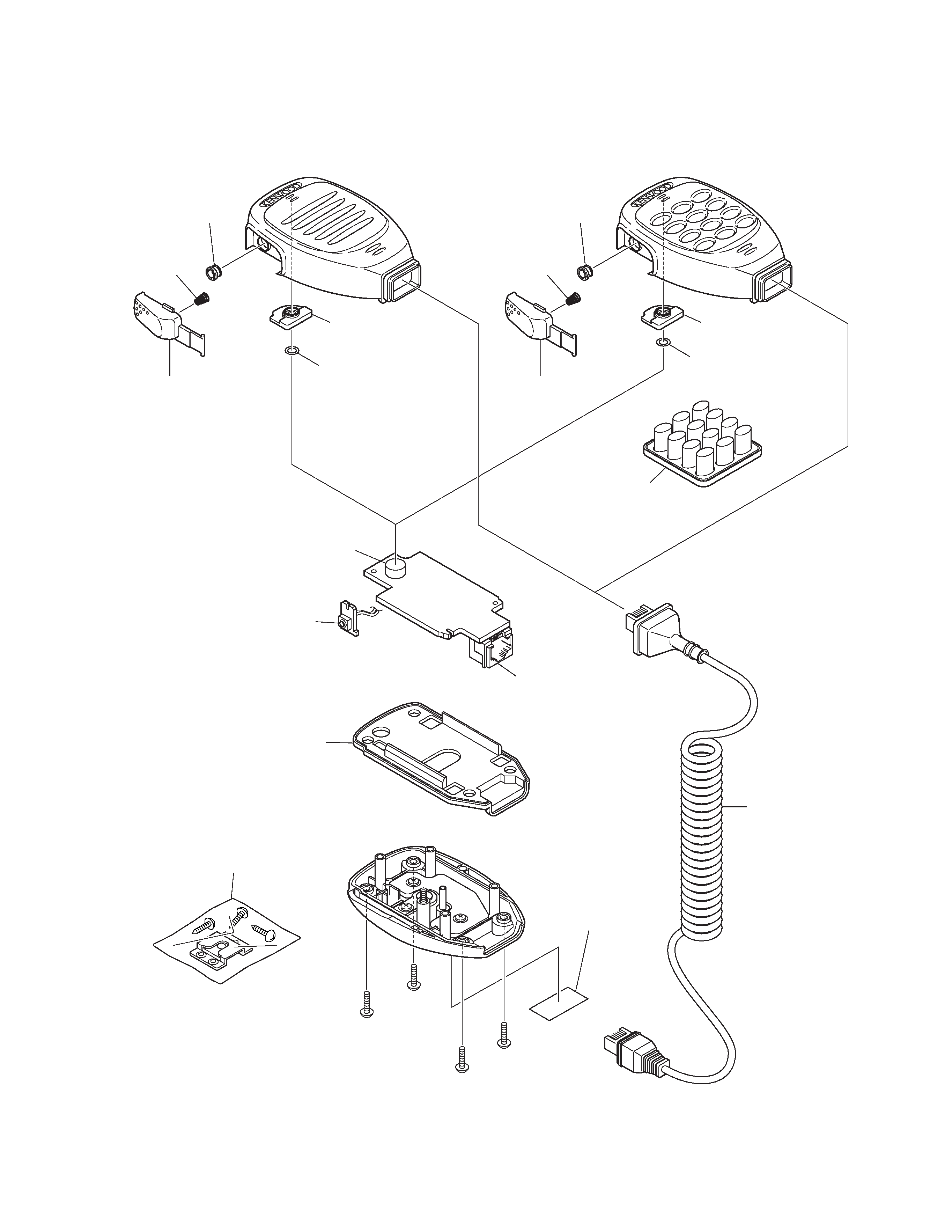
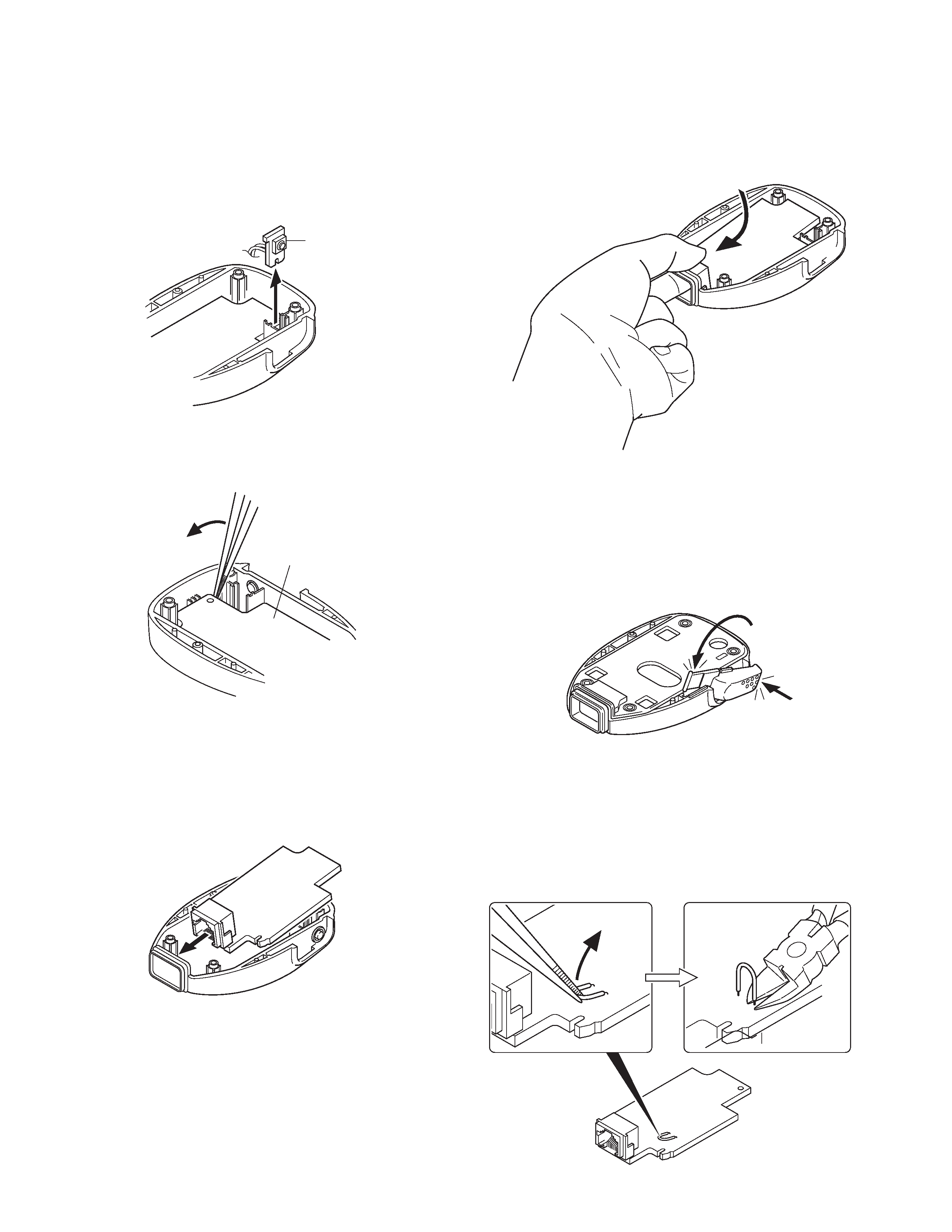
KENWOOD KMC36 Service Manual

Cover page of KENWOOD KMC36 Service Manual

Service Manual for KENWOOD KMC36, downloadable as a PDF file.

Manual details

  • Immediate download after payment.
  • Delivered as a PDF file.
  • The manual has 6 pages
  • File size: 0.21 MB
  • Available language versions: English
  • Different language versions may vary sligthly in file size and page count.

We guarantee that...

  • our manuals are complete,
  • the manual includes circuit diagrams,
  • our manuals are checked with antivirus,
  • We'll issue refund if the manual is damaged, incomplete or unreadable (our refund policy)

Sample pages

Thumbnail of page 1Thumbnail of page 2Thumbnail of page 3Thumbnail of page 4
Thumbnail of page 5Thumbnail of page 6Thumbnail of page 7Thumbnail of page 8
Thumbnail of page 9
background image
© 2004-7 PRINTED IN JAPAN
B51-8697-00 (N) 1309
MICROPHONE / KEYPAD MICROPHONE
KMC-35/36
SERVICE MANUAL
1
E30-7531-08
CURL CABLE
2
E58-0475-05
MODULAR JACK
3
G01-4546-08
COIL SPRING (PTT)
4
G53-1646-08
PACKING
5
J19-5479-08
MIC HOLDER
6
J19-5482-05
MIC HANGER (ACCESSORY)
7
K29-9333-08
LEVER KNOB (PTT)
8
K29-9334-08
KNOB (PTT)
9
K29-9335-08
KEY TOP
KMC-36
A
N52-3012-60
PAN HEAD TAPPING SCREW
10
S70-0499-08
TACT SWITCH
11
T91-0538-05
MIC ELEMENT
New
parts
Ref. No.
Parts No.
Description
Destination
KMC-35 (Y58-3740-20), KMC-36 (Y58-3750-20)
: New parts
PARTS LIST
KMC-35
KMC-36
Lever knob (PTT)
(K29-9333-08)
Curl cable
(E30-7531-08)
Lever knob (PTT)
(K29-9333-08)
Curl cable
(E30-7531-08)
Key top
(K29-9335-08)
background image
KMC-35/36
2
Main PCB removal
1. Remove the four screws, the rear case and all-round pack-
ing.
2. Lift the switch PCB and remove it from the front case.
( q )
q
Switch PCB
w
Main PCB
q
w
q
w
DISASSEMBLY FOR REPAIR
3. Lift the upper part of the Main PCB using a pair of twee-
zers ( w ) and remove the Main PCB.
Main PCB installation procedure
1. Install the microphone holder, spacer and keytop (KMC-36
only) on the front case.
2. Tilt the Main PCB and fit the modular connector into the
front case first.
3. Hold the modular connector with your fingers and move it
in the direction indicated by the arrow to install the Main
PCB onto the front case.
PTT knob installation procedure
1. Place the PTT knob in the front case diagonally as shown
in the figure.
2. Hold down the upper part of the PTT knob ( q ) and push
the PTT knob shaft down ( w ) to install the PTT knob onto
the front case.
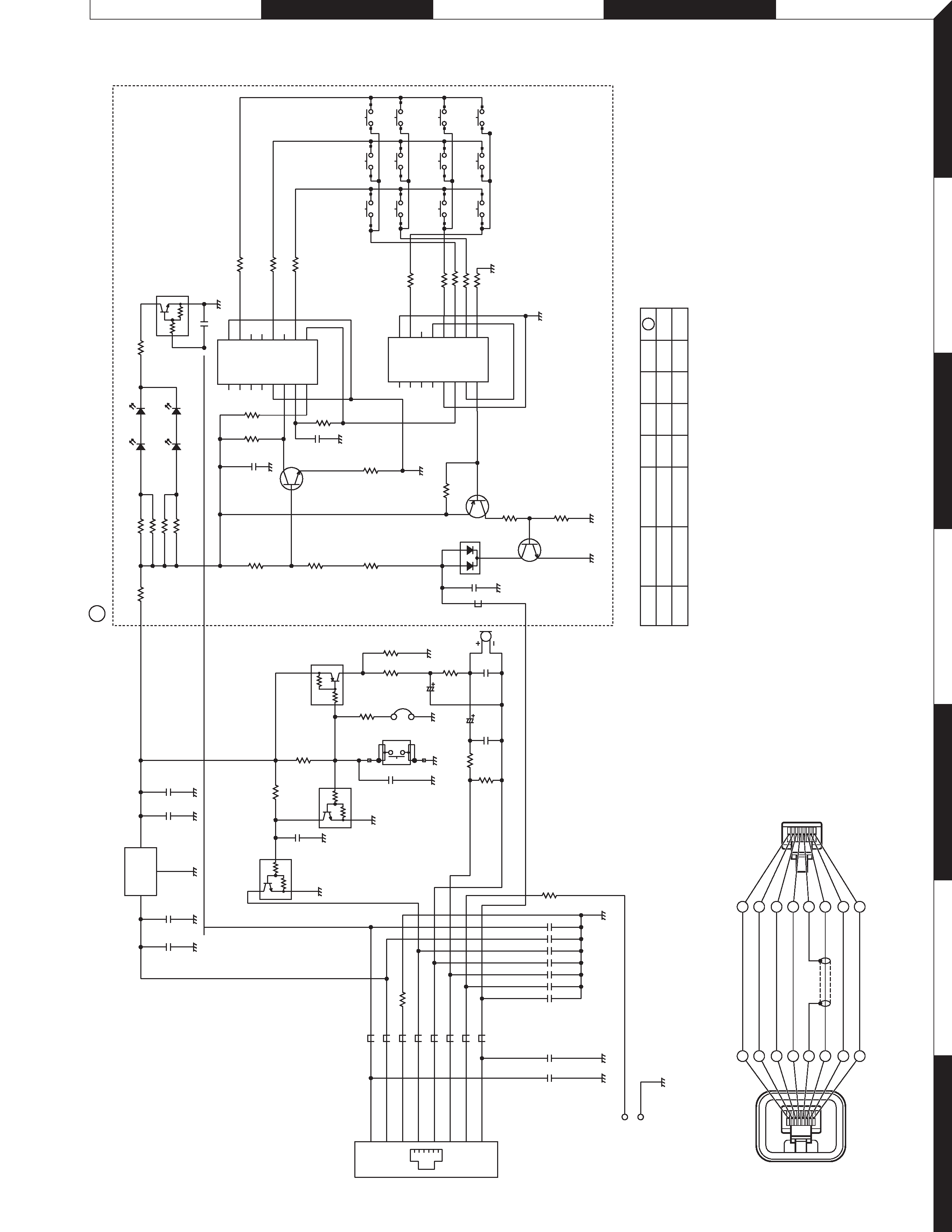
Hot microphone modification procedure
1. Lift the jumper with a pair of tweezers or similar tool. ( q )
Note : The jumper is bonded to the board, but not strongly
fixed, so it can be detached by applying light force.
2. Cut the base of the jumper into two parts with a pair of
nippers or similar tool. ( w )
background image
KMC-35/36
3
Hot Microphone Function
In the Hot microphone state, only microphones whose
PTT switch is pressed can send modulation signals in the
environment in which several microphones are connected to
the transceiver in parallel.
In the Normal microphone state, if the PTT switch on one
of the microphones is pressed, modulation signals are sent
from all microphones.
CIRCUIT DESCRIPTION
Q1
DTC114EUA
R1 10k
5V
R2
10k
R3
10k
R5
10k
R4
3.9k
R7
3.9k
R8
1k
R9
1.5k
R10
0
R6
0
*C5
C6
1000p
C12
1000p
C13
1000p
C14
1000p
C18
1000p
C17
100p
C10
0.068u
C7
1u 16
C9
10u 16
*L1
L2
L3
L4
L5
L6
L7
*L8
*C16
*C19
*C15
MIC
T91-0538-05
Q2
DTC144EUA
Q3
DTA144EUA
S70-0499-08
J1
E58-0475-05
1 BLC
2 SB
3 GND
4 PTT
5 ME(MIC GND)
6 MIC
7 HK(HOOK)
8 DM
C20
1000p
C11
470p
S1
PTT
SW
JP1
Circuit description
Hot microphone operation can be performed by cutting
the jumper (JP1).
If the jumper is not cut (Normal microphone state), bias
voltage is always applied to the microphone element (Q3 is
always ON) and if the microphone mute of the transceiver to
which the KMC-35/36 is connected is released, modulation
signals can be sent even when the microphone PTT switch is
not pressed.
If the jumper is cut (Hot microphone state), bias voltage is
applied to the microphone element only when the PTT switch
is pressed (Q3 turns ON only when the PTT SW is pressed),
and modulation signals cannot be sent when the microphone
PTT switch is not pressed.
background image
KMC-35/36
4
1 Curl cable
(E30-7531-08)
2 Modular jack
(E58-0475-05)
3 Coil spring (PTT)
(G01-4546-08)
4 Packing
(G53-1646-08)
5 MIC holder
(J19-5479-08)
700 Spacer
7 Lever knob (PTT)
(K29-9333-08)
8 Knob (PTT)
(K29-9334-08)
9 Key top
(K29-9335-08)
A M3 x 12 : N52-3012-60
10 Tact switch
(S70-0499-08)
11 MIC element
(T91-0538-05)
3 Coil spring (PTT)
(G01-4546-08)
5 MIC holder
(J19-5479-08)
700 Spacer
7 Lever knob (PTT)
(K29-9333-08)
8 Knob (PTT)
(K29-9334-08)
A
A
A
A
701 Model name plate
6 MIC hanger
(J19-5482-05)
Parts with the exploded numbers larger than 700 are not supplied.
EXPLODED VIEW
KMC-35
KMC-36
background image
SCHEMATIC DIAGRAM
KMC-35/36
5
7
6
5
4
3
2
1
E
D
C
B
A
Q1
DTC114EUA
R1
10k
R2
10k
R3
10k
R5
10k
R4
3.9k
R7
3.9k
R8
1k
R9
1.5k
R10
0
R6
0
C1
1000p
C4
1000p
*C5
C6
1000p
C12
1000p
C13
1000p
C14
1000p
C18
1000p
C2
0.1u
C3
0.1u
C17
100p
C10
0.068u
C7
1u
16
C9
10u
16
IC1
NJM78L05UA
2
COM
3
IN
1
OUT
*L1
L2
L3
L4
L5
L6
L7
*L8
*C16
*C19
*C15
HANGER
KNOB
HANGER
PLATE
*IC21
TC4017BF
1
Q5
2
Q1
3
Q0
4
Q2
5
Q6
6
Q7
7
Q3
8
VSS
9
Q8
10
Q4
11
Q9
12
CAR
13
INH
14
CLK
15
RST
16
VDD
*IC22
TC4017BF
1
Q5
2
Q1
3
Q0
4
Q2
5
Q6
6
Q7
7
Q3
8
VSS
9
Q8
10
Q4
11
Q9
12
CAR
13
INH
14
CLK
15
RST
16
VDD
*R29
1.5k
*R30
1.5k
*R31
1.5k
*R34
1.5k
*R35
1.5k
*R36
1.5k
*R38
1.5k
*R39
2.7k
*R33
22k
*C22
1000p
*Q21
2SC2712
(Y)
*Q23
2SC2712(Y)
*Q22
2SA1162(Y)
*R37
1k
*R27
1k
*R40
10k
*R32
10k
*R42
47k
*D23
*D24
*D26
*D27
*C25
100p
*C26
1000p
*R26
220k
*R28
33k
*D25
1SS184
*R22
100
*R23
100
*R24
100
*R25
100
*R41
0
*Q24
DTC114EUA
*R21
0
*C211000p
MIC
T91-0538-05
Q2
DTC144EUA
Q3
DTA144EUA
S70-0499-08
J1
E58-0475-05
1
BLC
2
SB
3
GND
4
PTT
5
ME(MIC
GND)
6
MIC
7
HK(HOOK)
8
DM
L9
C20
1000p
C11
470p
*R43
0
*R44
0
A
L92-0444-05
L92-0444-05
S1
PTTSW
1
23
45
6
7
8
9
*
0
#
1000p
1000p
100p
1000p
JP1
NO
NO
NO
NO
NO
NO
NO
YES
KMC-35
KMC-36
L1
L8
C5
C15
C16
C19
A
3
2
4
5
6
7
8
3
1
2
4
5
6
7
8
1
GREEN
RED
BLACK
BLUE
SHIELD
WHITE
GRA
Y
YELLOW
PTT
E
MIC-E
MIC
HK
CORD
ASSEMBLY
8P
MODULAR
PLUG
8P
MODULAR
PLUG

Reviews

There are no reviews of this manual yet.