3
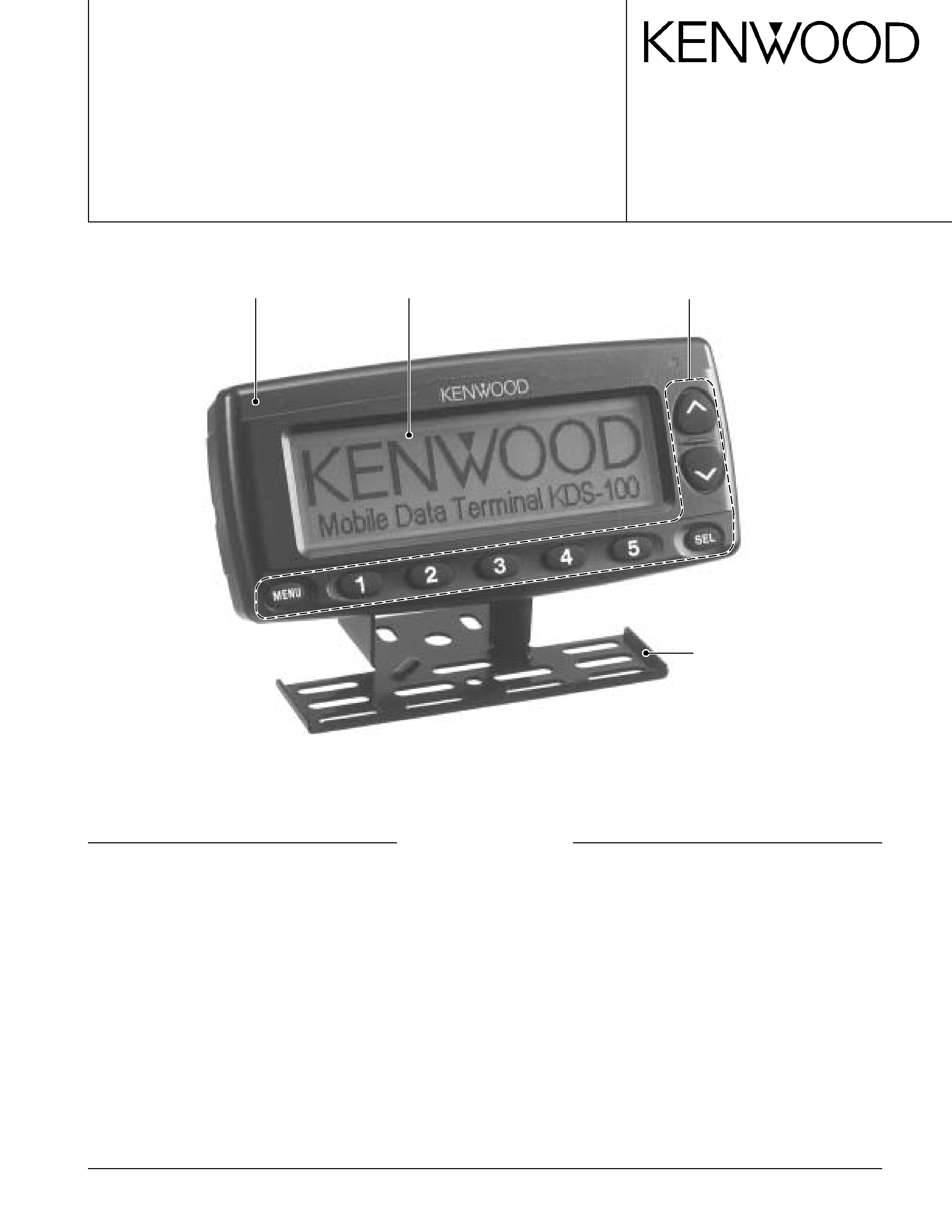
KDS-100
INSTALLATION / REALIGNMENT
TK-760G/762G/860G/862G/768G/868G Series
(TK-*60G Series)
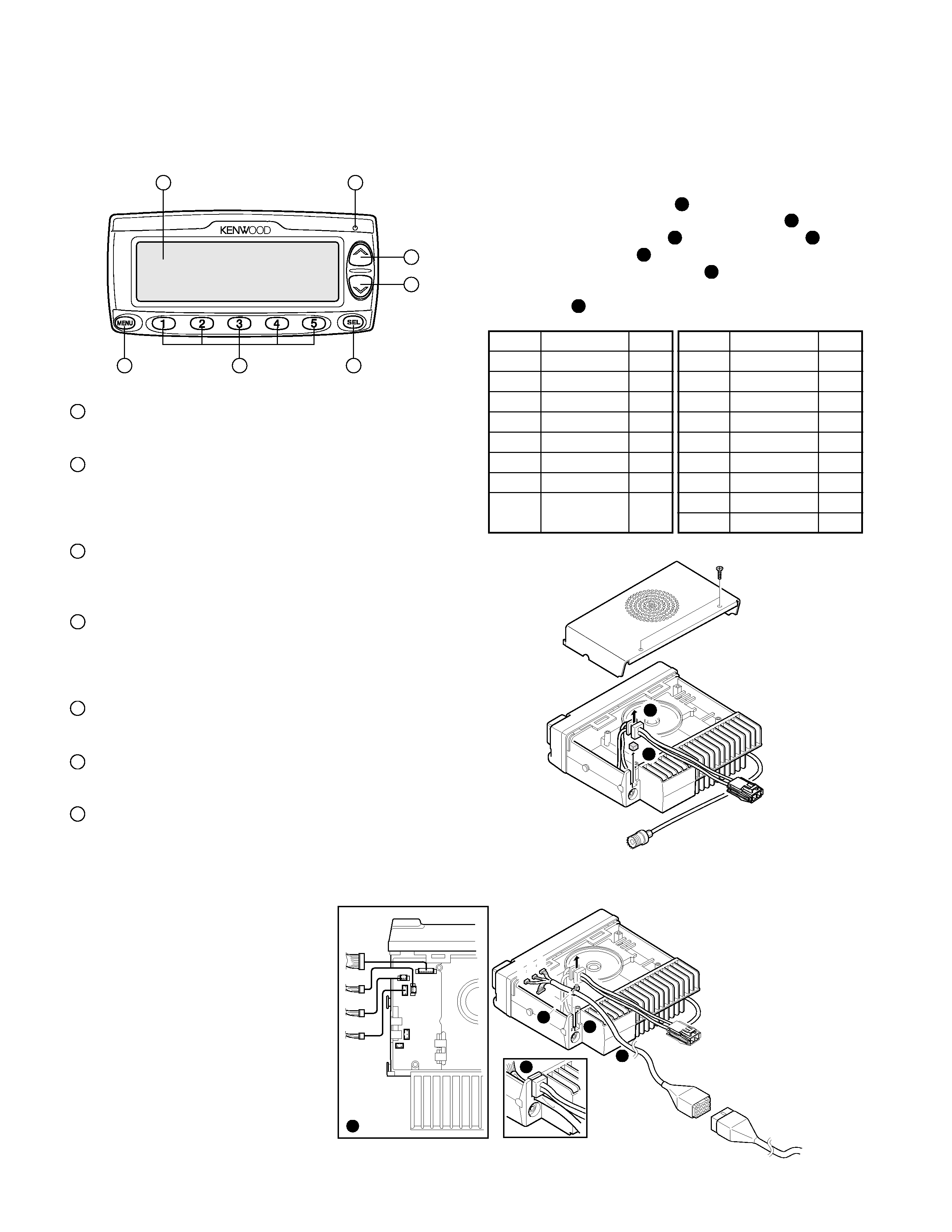
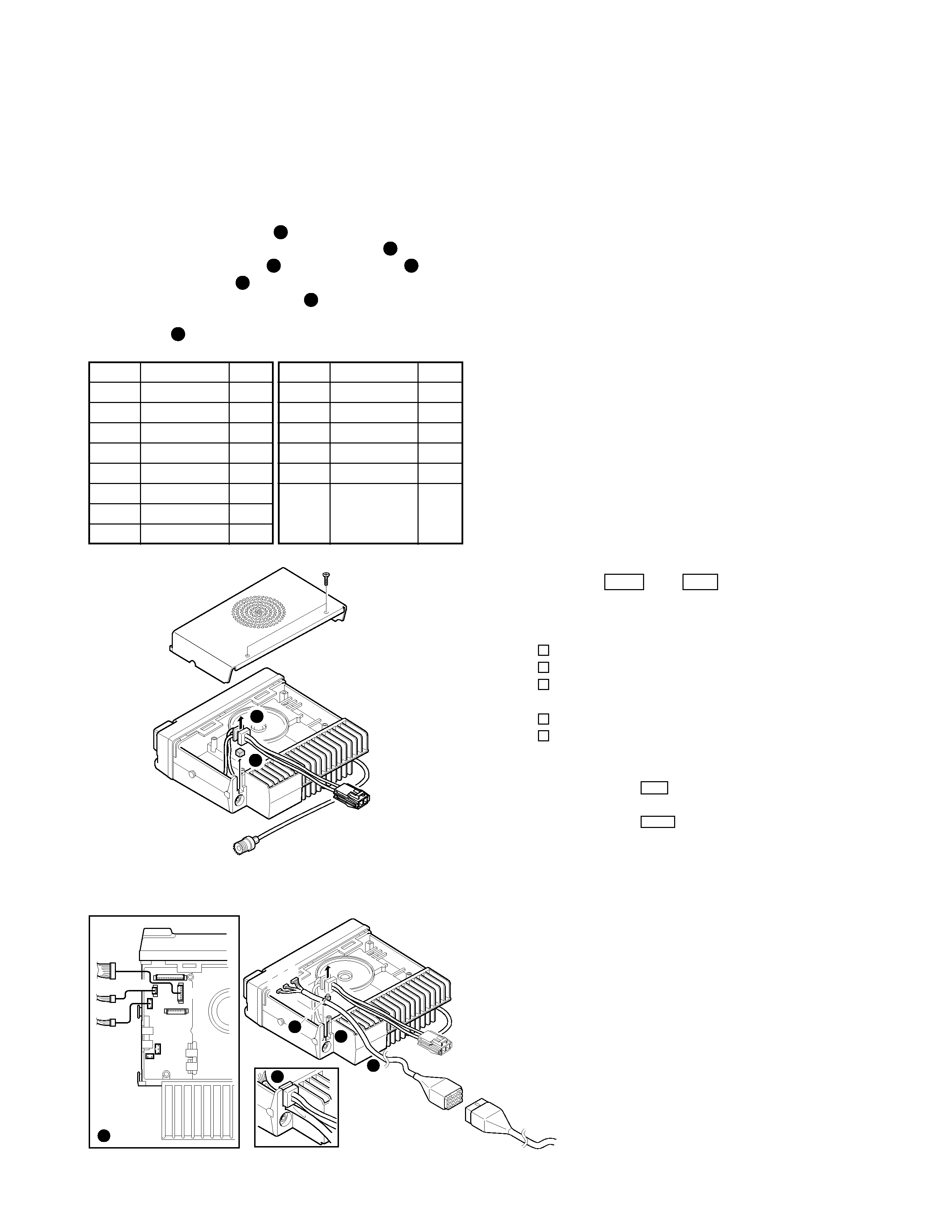
s Installing the KCT-35 in the Transceiver
1. Remove the upper cover from the transceiver.
2. Lift the DC cord bushing ( 1 ) from the chassis.
3. Remove the pad as shown in the Figure 3 ( 2 ).
4. Insert the KCT-35 cable ( 3 ) into the chassis ( 4 ). The
wire harness band ( 5 ) must be inside the chassis.
5. Replace the DC cord bushing ( 6 ).
6. Connect the KCT-35 to the TX-RX unit (A/2) as shown in
Figure 4 ( 7 ).
Fig. 3
1
2
Fig. 4
A
B
C
3
4
6
7
5
KDS-100 or
through KCT-36
extension cable.
KCT-35
1
13
15
3
CN5
A
B
C
CN4
CN3
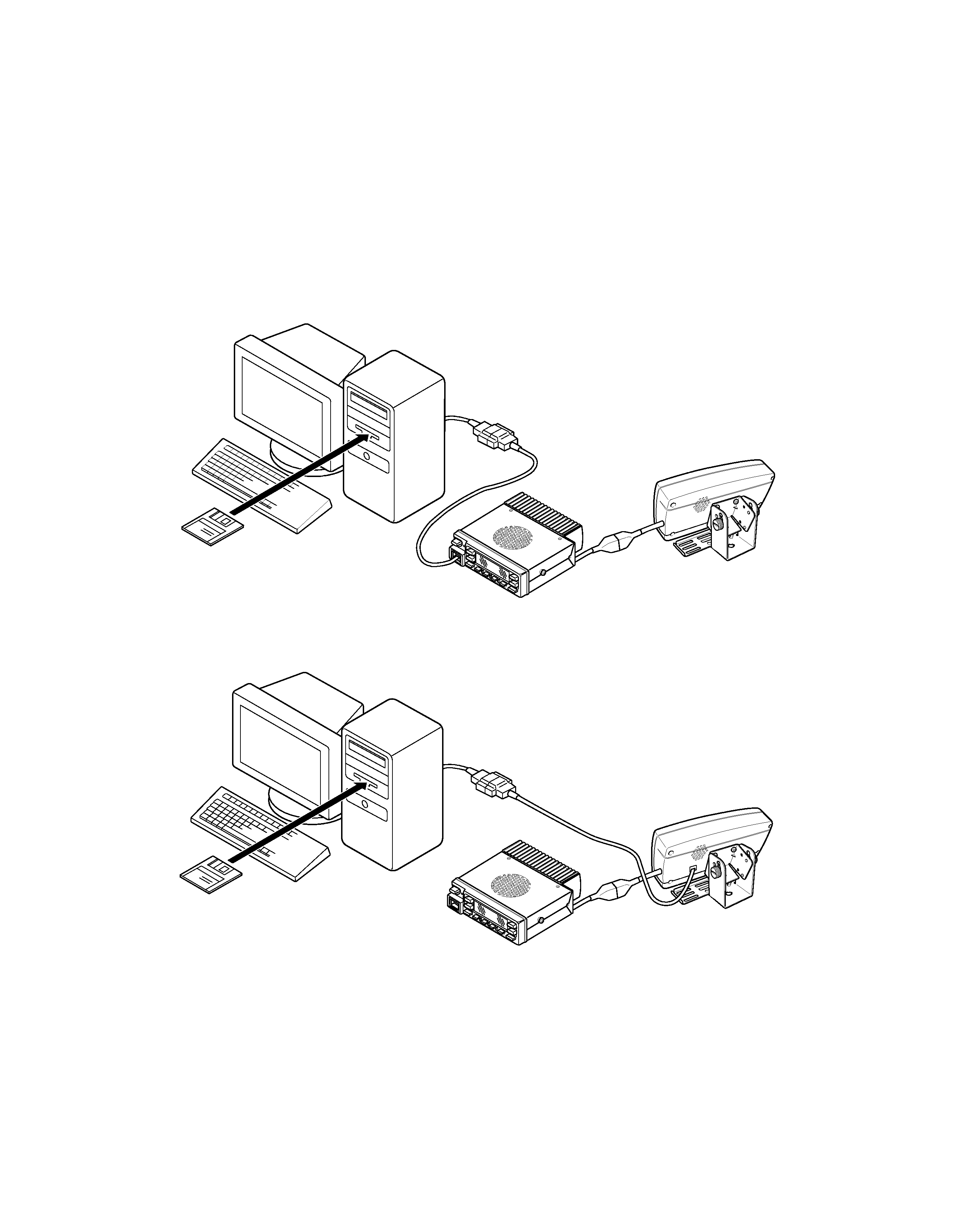
Transceiver Setting
When the KDS-100 (Mobile Data Terminal) is connected
to a transceiver, the transceiver functions must be set. The
transceiver FPU is used to make this setting.
For a connection method, see Figure 1.
s TK-*80 Series Setting Method
1. Setting with KPG-49D (K and M markets FPU)
1) Select "Optional Features" from the "Edit" menu and
set COM1 (Internal Port) "[None]" to "[Data]".
2) Select "FleetSync" from "Edit" and set functions to
"Yes/No" as follows:
Status Message Stack ................... [No]
Short Message Stack ..................... [No]
Caller ID Stack ................................ [No]
Status Message Serial Output ....... [Yes]
Short Message Serial Output ........ [Yes]
3) Enter an ID.
Fleet (Own): A three-digit number between 100 and 300
can be entered in [
].
ID (Own): A four-digit number between 1000 and 4999
can be entered in [
].
2. Setting with KPG-60D (E markets FPU)
1) Select "Extended Function" from the "Edit" menu and
set COM1 " None " to " Data ".
2) Select "Digital Message System" from "Edit" and set
the checkboxes as follows:
· Uncheck items.
Status Message Stack
Short Message Stack
Selcall ID Stack
· Check items ().
Status Message Serial Output
Short Message Serial Output
3) Enter an ID.
Fleet (Own): A three-digit number between 100 and 300
can be entered in
.
ID (Own): A four-digit number between 1000 and 4999
can be entered in
.
Connector
Wire Color
Pin No.
A-1
Brown
4
A-2
Green
7
A-3
NC
A-4
Orange
5
A-5
NC
A-6
NC
A-7
Yellow
6
A-8
Blue
8
Connector
Wire Color
Pin No.
B-1
Gray
10
B-2
White
11
B-3
Purple
9
C-1
NC
C-2
Black
3
C-3
Red
1