TEST MODE
1.Entering the test mode
Reset the unit by pressing the FM key and the Preset 6 key
at the same time.
When the test mode is entered, all indicators light up.
2.Releasing the test mode
Reset the unit by pressing the Preset 6 key.
Note: The unit cannot be reset by simply turning ACC off,
turning power off, or turning power off for a brief
moment.
3.Voltage adjustment on the FM S-meter
(1) Enter the test mode.
(2) While pressing the Preset 1 key, keep on pressing the
Preset 6 key.
(3) When the adjustment is made, "ADJ OK" is displayed.
When adjustment cannot be made, "ADJ NG" is
displayed.
4.Writing SD voltage for the AM
(1) Enter the test mode.
(2) While pressing the Preset 1 key, keep on pressing the
Preset 6 key, which results in writing SD.
5.Forced switching of K2I Auto/Manual
In tuner-mode, keeping on pressing TI key, and the Auto
and Manual modes can be swieched. The initial condition
is manual modes, which is indicated by flashing DUAL dots.
6.Forced narrow/wide switchng of K2I
In tuner-mode, when Preset 6 is pressed, forced narrow/
wide mode switching is made. The initial condition is in wide
mode and the NEWS dot flashes.
7.CD receiver test mode specification
By pressing the track-up key, the unit jumps to the following
tracks:
No. 9 No. 15 No. 10 No. 11 No. 12 No. 13
No. 14 No. 9 (Goes back to the first position.)
When the track-down key is pressed, the unit jumps to the
previous track.
8.MD test mode specification
After loading MD, the unit plays No. 7. Then, the unit jumps
as follows each time it track-ups.
No. 2 No. 13 No. 23 No. 30 No. 34
No. 7 (Goes back to the first position.)
When the track-down key is pressed, the unit jumps to the
previous track.
9.Tape test mode
In the initial step, the blank skip is turned off.
10.Audio-related items
· The volume is -10dB (on display, it is 30).
· The loudness is off and CRSC is off regardless of
functions.
· Buss/treble and balance/fader are to be adjusted by the
up/down key to full-boost/fullcut and fullfront/fullrear
respectively.
· The high-pass filter is adjusted by the up-key to
throughput/100Hz/200Hz and, by the down-key, to
200Hz/100Hz/throughput.
· Other adjustments are the same as before.
11.Backup current measurement
When reset in ACC-off condition (backup is on), the mute
terminal goes off after 2 seconds instead of 15 seconds,
when the ACC is tuned off in the test mode. (In this case,
the panel/CD/C/MD mechanisms are not activated.)
12.Registering security code after changing
E2PROM at the services (Only for type
M. However, RDS models are excluded)
(1) Put the unit into the test mode (Refer to 1. Above for
how to enter the test mode.)
(2) Press SRC key to put the unit into the tuner mode.
(3) Press Audio key for one second and put the unit into
the menu mode.
(4) Press FM/AM key and then select "SECURITY."
(5) Press track up/down key for full 2 seconds.
(6) Press Preset 1, Preset 2, Preset 3, and Preset 4 and
then input codes.
Example: Inputting "3510."
· Preset 1 key 4 times.
· Preset 2 key 6 times.
· Preset 3 key 2 times.
· Preset 4 key once.
(7) Press DISP key for 3 seconds and confirm that
"APPROVED" is displayed.
(8) Release the test mode. (Refer to "2. Releasing the test
mode" above.)
13.Simplified method for clearing the
security code (Only for type K)
(1) When code is requested, continue pressing VOL UP
key for three seconds while pressing the DISP key.
(.... disappear.)
(2) Input "KCAR," using the remote controller (the same
as the 98 Model)
· Press Tenkey 5 twice and then press track-up key.
(Inputting "K")
· Press Tenkey 2 three times and then press track-up
key. (Inputting "C")
· Press Tenkey 2 once and then press track-up key.
(Inputting "A")
· Press Tenkey 7 twice and then press track-up key.
(Inputting "R")
(3) Then, the security is released and the unit goes into
the Tuner Mode.
14.Writing MASK KEY on line (E2PROM in
initial codition)
(1) While pressing the FM key and Preset 6 key, press
reset key to enter the test mode.
(2) Press AUDIO key for full one second to put the unit
into the menu mode.
(3) Select the "MASK KEY," using the FM key or AM key.
(4) Press on the track up/down key to display "TRANSMIT 1."
(5) Point the MASK KEY to the light receptor and press it
for 0.5 second or longer.
(6) When "TRANSMIT 2" is displayed, press MASK KEY
for 0.5 second or longer. When this is conducted, the
counter codes for the first time and the second time
will not be compared.
(7) When "APPROVED" is displayed, writing is completed.
Time the demonstration mode is set and the test mode
is released.
Note: After an elapse of 30-minuite period, during
which no code is written, an error is effected
and the device will power off.
15.Releasing MASK KEY requests (When
reset or backup is off when MASK KEY is
approved)
(1) When power is turned on, "TRANSMIT 1" is displayed
and the unit goes into MASK KEY request mode.
(2) Point the MASK KEY to the light receptor and press it for
more than 3 seconds (until the level display indicates full)
(3) When "TRANSMIT 2" is displayed, press the MASK
KEY again for more than three seconds. At this point,
when "TRANSMIT 1" is displayed, repeat the process
in (2) above for the second time.
(4) When "APPROVED" is displayed, MASK KEY is
approved and the unit turns power on.
16.Initializing MASK KEY (returning to the
default condition from MASK KEY
approved state)
(1) While pressing the FM key and Preset 6 key at the
same time, press RESET to enter the test mode.
(2) "TRANSMIT 1" is displayed and the unit goes into
MASK KEY request mode. The display at this point will
be "
**" instead of "[ ]".
(3) Use MASK KEY release remote controller for more than
three seconds.
(4) When "TRANSMIT 2" is displayed, press the MASK
KEY for more than three seconds for the second time.
(5) When "APPROVED" is displayed, the MASK KEY is
released and the demonstration mode is set. Then, the test
mode is released, returning the unit into default condition.
17.Clearing from the MASK KEY
(1) While pressing FM key and Preset 6 key at the same
time, press RESET to enter the test mode.
(2) Press the AUDIO key for full one second to put the unit
into the menu mode.
(3) Select MASK KEY, using track up/down key.
(4) Press on the FM key or AM key for full two seconds
and the unit will display "TRANSMIT 1."
(5) Point the MASK KEY release controller to the light
receptor and press it for 3 seconds or longer. (Until the
level display indicates full.)
(6) When "TRANSMIT 2" is displayed, press MASK KEY
for 3 seconds or longer for the second time. If
"TRANSMIT 1" is displayed, start again from (5) above.
(7) When "APROVED" is displayed, E2PROM is cleared.
The unit goes back to the condition described in Line
14: Writing MASK KEY on line (E2PROM in initial
condition)
18.Other
· Automatic panel closing does not occur in case a TAPE,
CD, or MD is inserted.
· Panel is opened/closed when ATT key is turned On/Off.
(A remote controller is used when turning ATT on.)
· The DNPP/SBF key of the remote controller (RC-510) is
used for tuning the menu mode On/Off.
· The OPEN/CLOSE key of the remote controller (RC-510)
is used for tuning the audio mode On/Off.
· The feed on the menu will be feeds only for necessary
features.
· "CODE OFF" and other displays will not be issued when
the power is turned on.
· The dimmer of the FL model and contrast on the LCD model
can be adjusted only for 0/5/10 by the UP/DOWN key.
TEST MODE
5
6
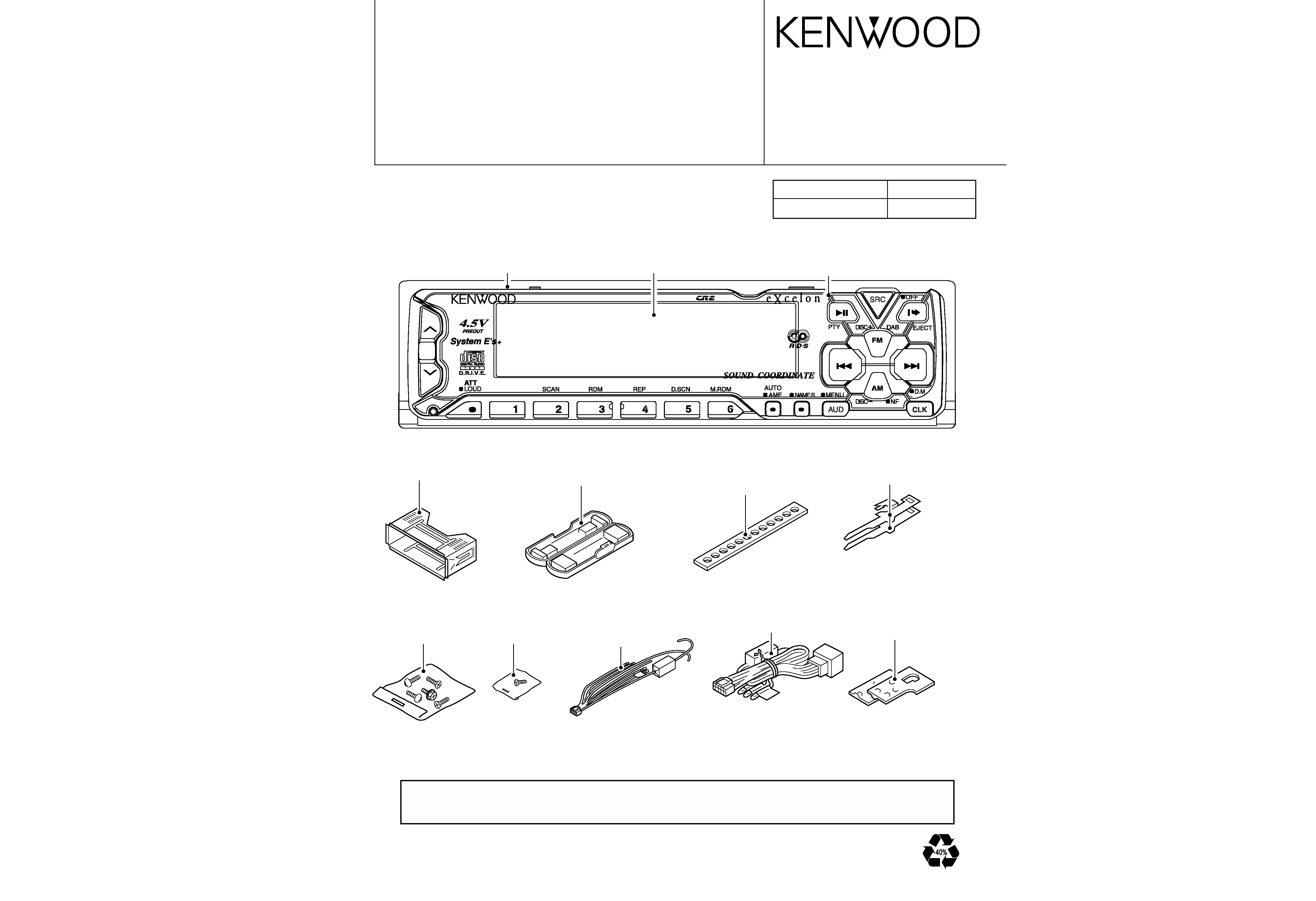
KDC-X915/X815/PS9016R/PS9080R
KDC-X915/X815/PS9016R/PS9080R