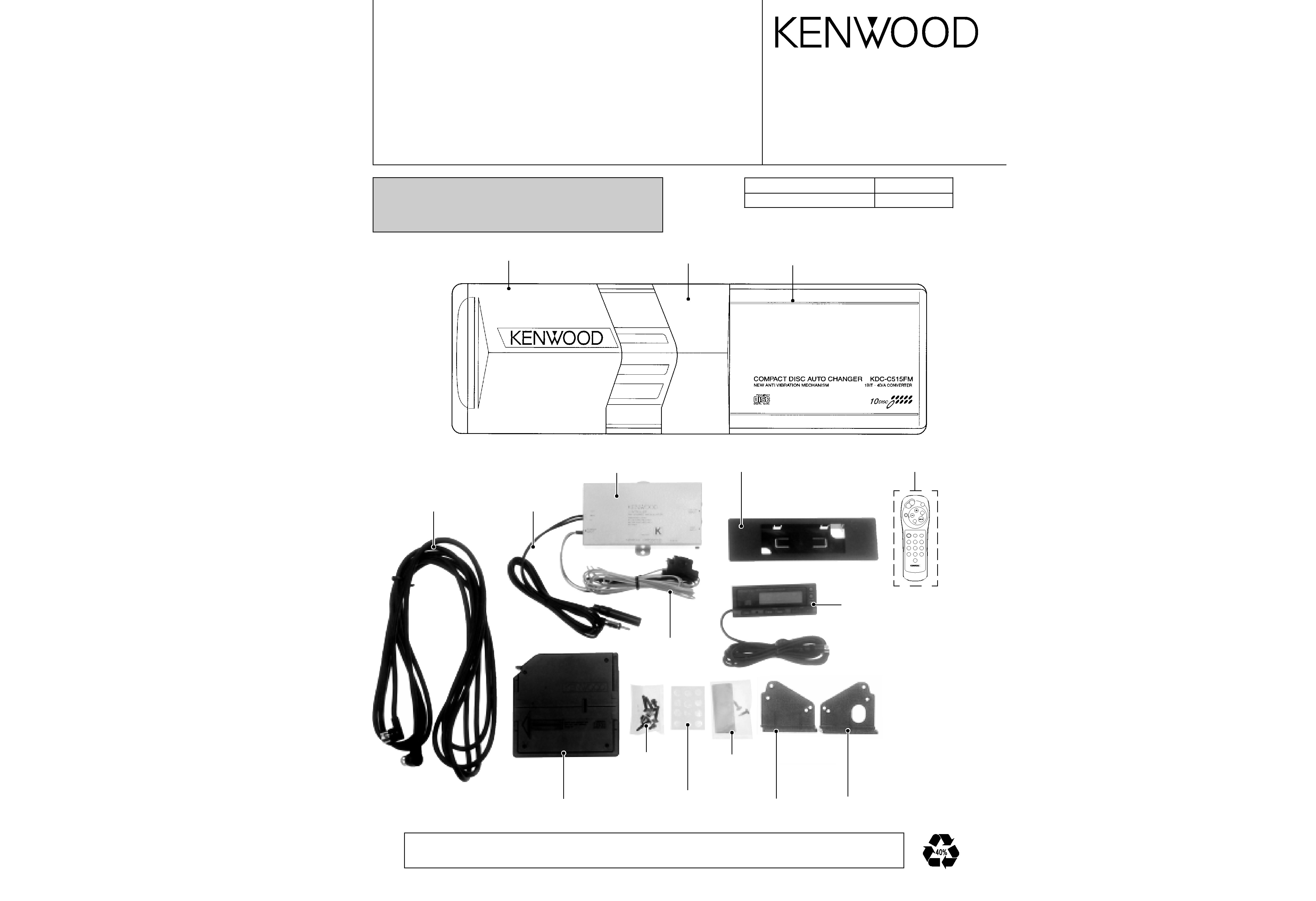
KDC-C515FM
KDC-C515FM
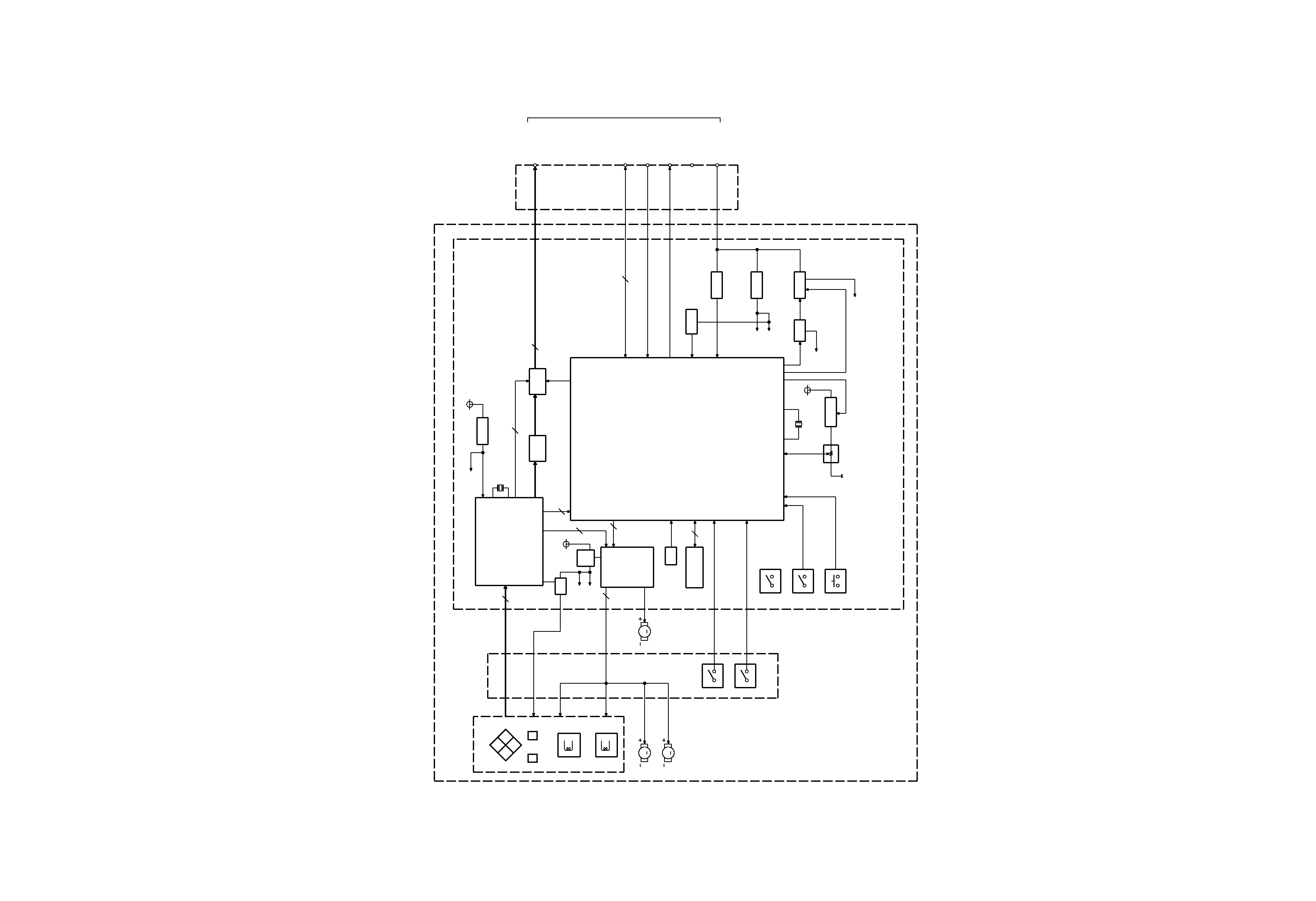
MICROCOMPUTER DESCRIPTION
ADJUSTMENT
5
6
q
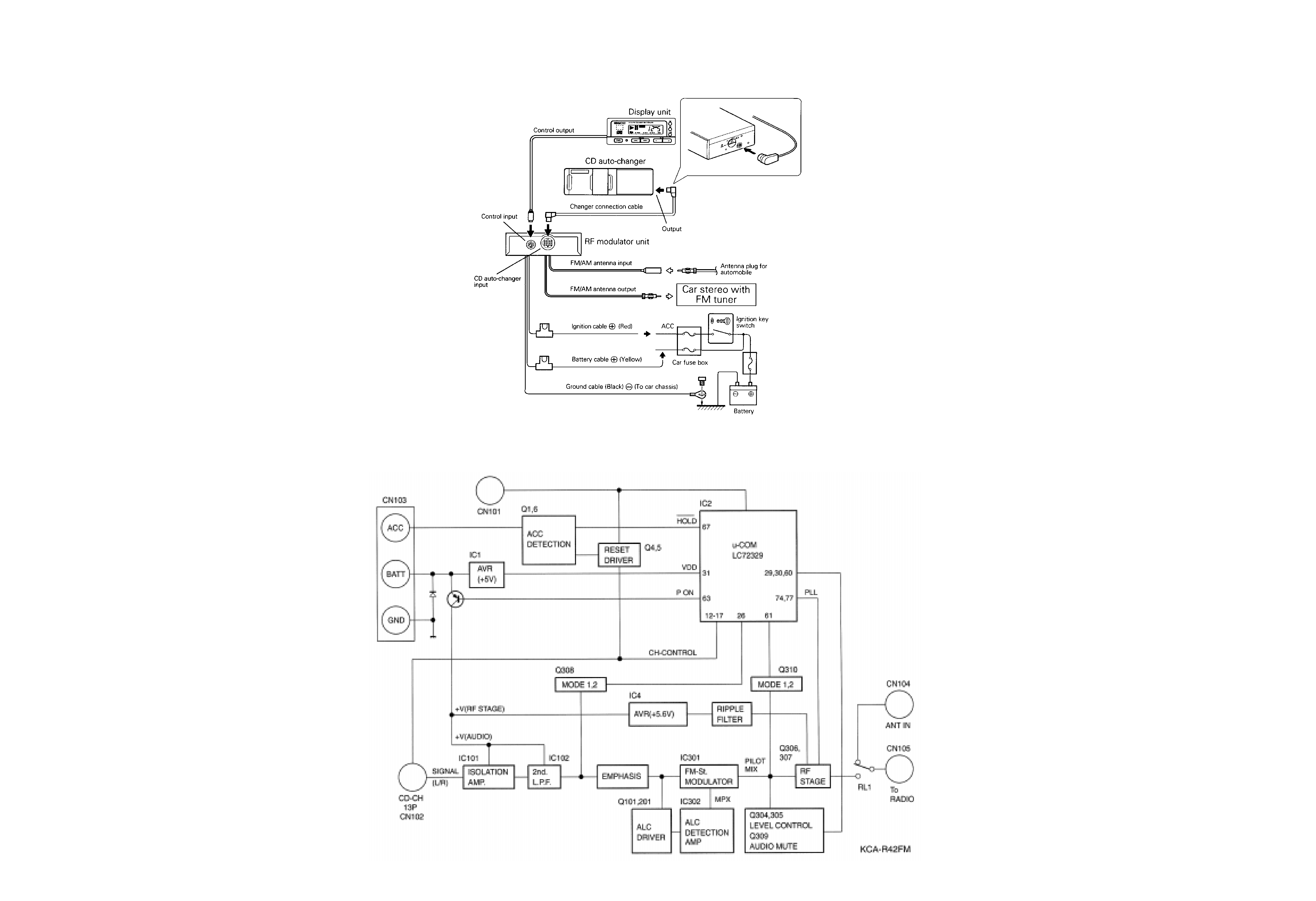
RF MODULATOR UNIT
1. DC balance adjustment (VR301)
While observing the waveform with a oscilloscope at
pin 13 of IC301, adjust VR301 to minimize the
waveform level.
2. PLL control voltage adjustment (VC301)
First set the transmission frequency to *87.9 MHz with
the commander, then adjust VC301 so that the DC
Voltage at the + pole of C317, measured using a
multimeter or digital tester, is + 3V (
± 0.1 V).
3. Modulation level adjustment (VR303)
The method using a standard receiver or tuner.
Adjust VR303 so that the output level from the
standard receiver or tuner is as specified.
System
µ-com : UPD784214GC (X32- : IC7)
qTerminal description
1
TOUT
O
Test output.
2
TSTB
O
Text data strobe signal.
3
-
O
NC.
4
FOK
I
H: Focusing OK. L: Focusing NG.
5
X OFF
O
H: Servo IC oscillation OFF.
6
RST
O
L: Servo IC reset.
7AO
O
H: Parameter setting.
L: Address register setting.
8
STB
O
L: Data latch.
9
VDD
Power supply connection.
10
X2
-
Oscillator.
11
X1
I
Oscillator.
12
VSS
I
GND.
13
XT2
-
NC.
14
XT1
GND.
15
RESET
I
L: Reset.
16
BSY
17
MGSW
I
H: Holder IN. L: Holder OUT.
18
EJSW
I
H: Eject.
19
COMMSW
I
H: New. L: Old.
20
PACK
I
Text data pack sync signal.
21
CHCON
I
Changer control.
22
BUDET
I
B-U detection.
23
AVDD
I
A/D converter power supply.
24
AVREF
I
A/D converter reference
voltage.
25
HOT
I
High temperature detection.
26
LPS
I
Position detection.
27
LOESW
I
L: Loading completed.
28
LIMSW
I
L: PU limit switch ON.
29
TOFF
I
Tracking off mode.
30
ADJSEL
I
H: Servo Adjustment OFF.
L: Servo Adjustment ON.
31
TBANK
I
H: Gain UP. L: Normal.
32
SIM3
33
AVSS
GND.
34
LPSCO
O
A/D converter power supply.
H: OFF.
35
AMUTE
O
L: Muting ON.
36
AVREF1
A/D converter power supply.
37
SDI
I
Servo data input.
38
SDO
O
Servo data output.
39
SCK
O
Servo clock output.
40
DATAH
I
Data input from H/U.
41
DATAC
O
Data output to H/U.
42
HCLK
I/O
H: Clock input.
L: Clock output.
Pin No.
Pin Name
I/O
Description
43
REQC
O
Communication request to
H/U.
44
CHMUTE
O
L: Muting ON.
45
TSO
O
Text data output.
46
TSI
I
Text data input.
47
TSCK
O
Text clock output.
48~55
A0~A7
O
S-RAM address setting.
56~63
D0~D7
I/O
S-RAM data input/output.
64~68
A8~A12
O
S-RAM address setting.
69~71
A13~A15
O
S-RAM enable control.
72
VSS
GND.
73, 74
A16, A17
O
S-RAM enable control.
75
RAMOK
O
H: OK.
76
ELVADJ
I
L: Adjustment mode.
77
RD
O
S-RAM read control.
78
WR
O
S-RAM write control.
79
WAIT
I
Wait during S-RAM access.
80
ASTB
O
NC.
81
VDD
Power supply connection.
82
RAMTEST
I
H: S-RAM check mode.
83
REQH
I
Communication request from
H/U.
84
SP/LO+
O
Spindle/Loading + control.
85
SP/LO-
O
Spindle/Loading - control.
86
ELV+
O
Mechanism UP/DOWN control.
87
ELV-
O
Mechanism UP/DOWN control.
88
SIM1
I
L: Text. H: No Text.
89
SEARCH
O
H: Play. L: Search.
90, 91
TEST1, 2
I
L: Normal. H: Test.
92
8V/7V
O
H: 7 V. L: 8 V (Servo power
supply).
93
SLG
I
H: +3 dB. L: 0 dB (Sled gain).
94
TEST/VPP
I
L: Flash ROM program mode
OFF.
95
SRVSEL
I
H: Servo mode.
96
SLNSA
I
L: Sled non-sensible area ON.
97
SDA
I/O
EEPROM data input/output.
98
SCL
O
EEPROM clock output.
99
PON
O
L: Power ON.
100
ARMSW
I
H: Arm switch ON.
Pin No.
Pin Name
I/O
Description
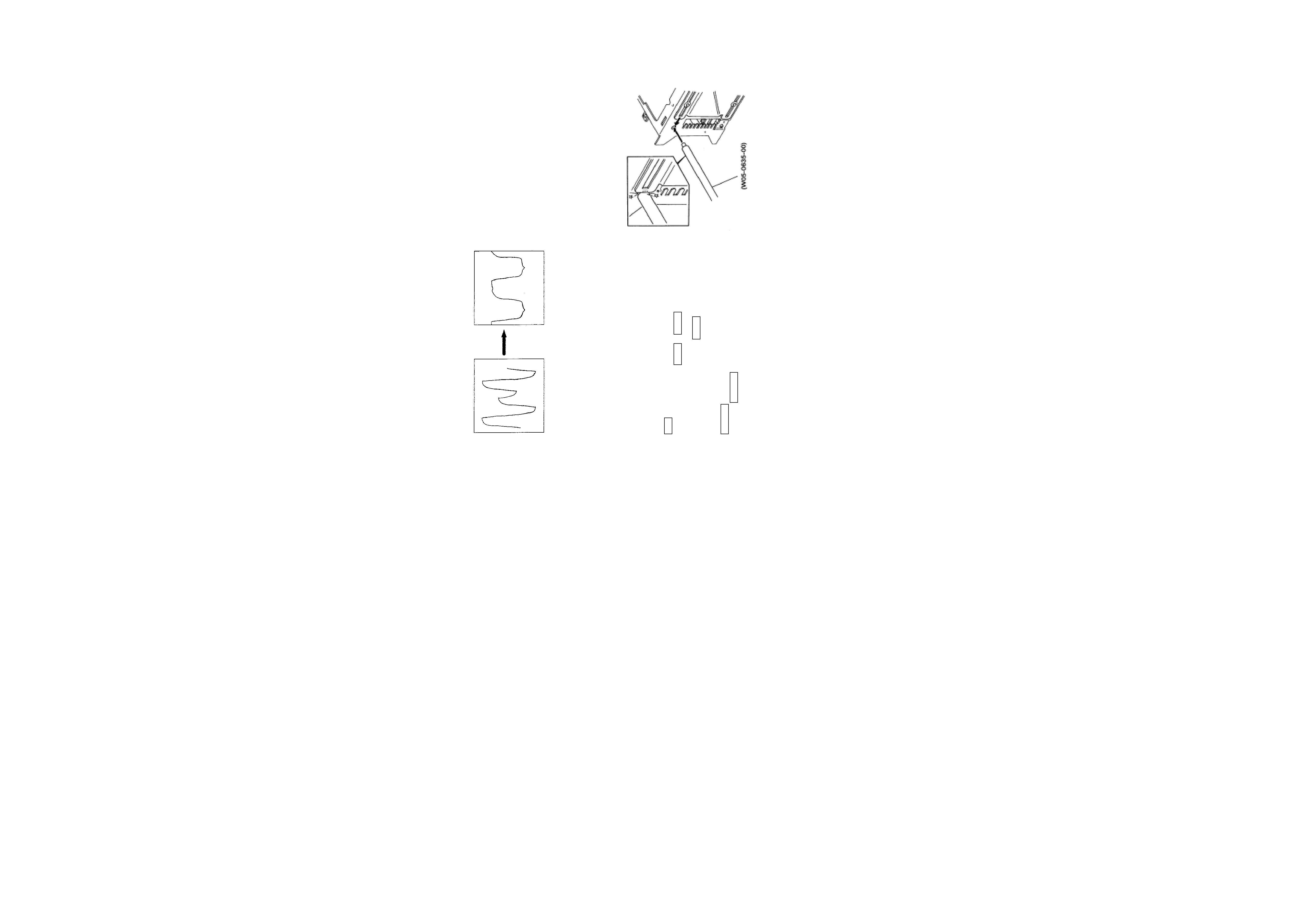
LPS initial position adjustment procedure
Connect the changer to the H/U. While holding the
magazine eject button of the changer, press the reset button
of the H/U and, in about 1 second, release the magazine
eject button. Press the CD button of the H/U to enter the
E-88 mode. Move the mechanism deck to around the 1st
stage by pressing the DISC- or DISC+ button.
Insert the adjustment tool into the tool hole on the changer
mechanism. Then press the DISC+ button to move the
mechanism deck until the mechanism's slider hits the
adjustment tool. When the motor locks (stops) press the
REPEAT key of the H/U.
When the REPEAT key is pressed, the mechanism moves
automatically to the 1st stage and the initial position
adjustment completes. (The data is written in the E2PROM
at this time.)
ADJUSTMENT