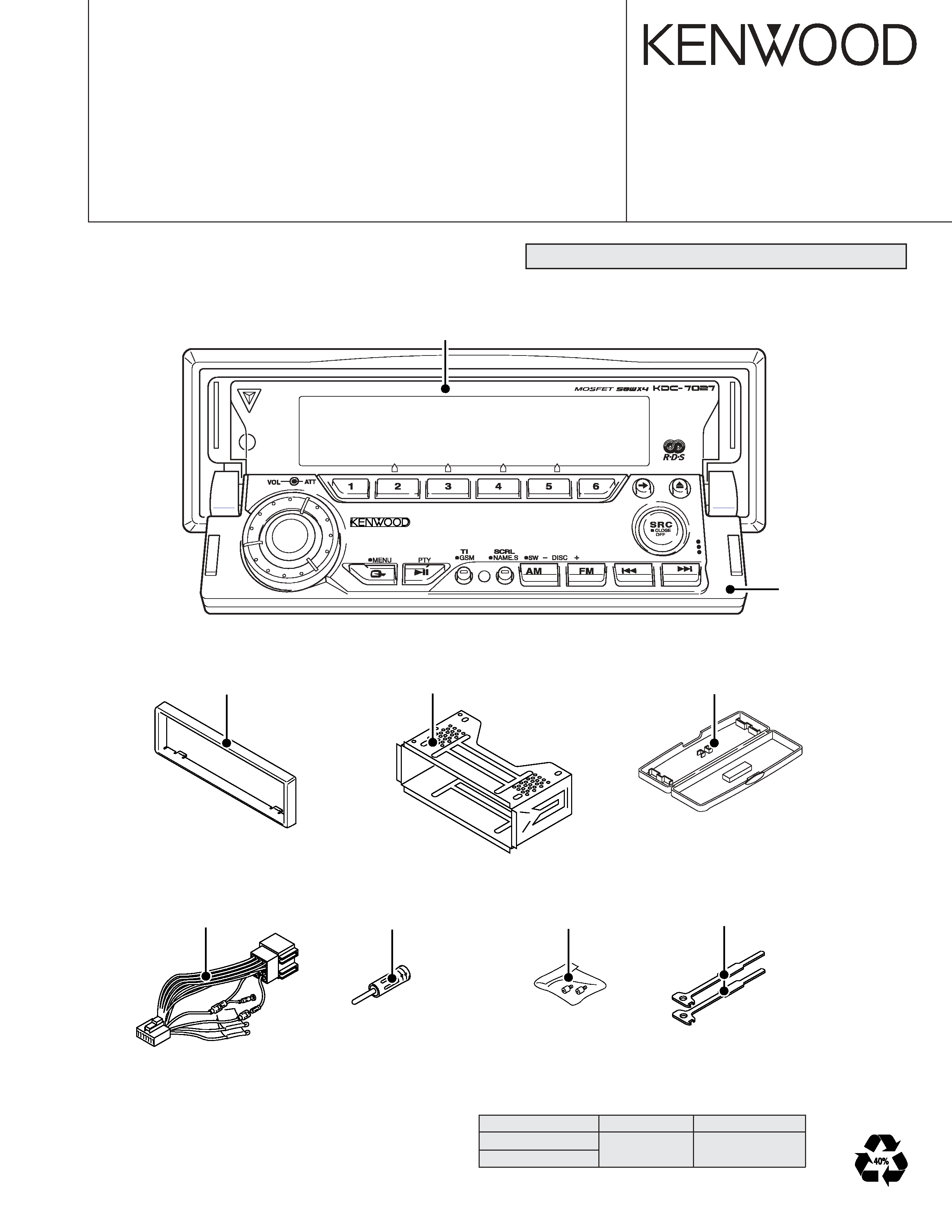
KENWOOD KDC-7027Y Service Manual

Cover page of KENWOOD KDC-7027Y Service Manual

Service Manual for KENWOOD KDC-7027Y, downloadable as a PDF file.

Manual details

  • Immediate download after payment.
  • Delivered as a PDF file.
  • The manual has 40 pages
  • File size: 1.81 MB
  • Available language versions: English
  • Different language versions may vary sligthly in file size and page count.

We guarantee that...

  • our manuals are complete,
  • the manual includes circuit diagrams,
  • our manuals are checked with antivirus,
  • We'll issue refund if the manual is damaged, incomplete or unreadable (our refund policy)

Sample pages

Thumbnail of page 1Thumbnail of page 2Thumbnail of page 3Thumbnail of page 4
Thumbnail of page 5Thumbnail of page 6Thumbnail of page 7Thumbnail of page 8
Thumbnail of page 9
background image
© 2004-02 PRINTED IN JAPAN
B53-0129-00 (N) 1839
CD RECEIVER
KDC-7027
KDC-7027Y
SERVICE MANUAL
Escutcheon
(B07-3078-01)
Plastic cabinet assy
(A02-2731-13)
Mounting hardware assy
(J21-9823-03)
DC cord
(E30-4942-05)
Panel assy
(A64-3253-02)
Panel assy
(A64-3234-01)
Antenna adaptor
(T90-0552-05)
Lever
(D10-4674-04) x 2
Screw set
(N99-1734-05)
CD mechanism extension cord (24PIN) : W05-0935-00
TDF PANEL INFORMATION
MODEL
PARTS NO.
PANEL NAME
KDC-7027
KDC-7027Y
Y33-1790-61
TDF-M7000
background image
KDC-7027/7027Y
2
TUNER
CD
CH
MECHA
PANEL
TDF UNIT
SWITCH UNIT
(X16-208)
(X16-256)
(X34- )
(X16-254)
DISPLAY
UNIT
BUFFER
RDS
DECODER
BUFFER
REMO
RESET SW
KEY MATRIX
FL
SYSTEM
MPX
E-VOL
&
ACC DET
TEL MUTE
B.U DET
SYSTEM
DRIVER
MUTE
POWER
IC
ACC
TEL MUTE
BACK UP
SP OUT (FL)
RESET
KEY ILL
IC14
IC2
IC1
IC4
IC8
IC9
Q303,304
AM+B
AGC
E'S+
PRE MUTE
PRE MUTE
PRE MUTE
PRE OUT
(FRONT)
PRE OUT
(REAR)
(SUB WOOFER)
PRE OUT
AUX IN
OP AMP
OP AMP
OP AMP
SP OUT (FR)
SP OUT (RL)
SP OUT (RR)
EXT AMP
DIMMER
DIMMER
EXT.AMP.CON
ANT-CON
ANT CON
P-CON
P CON
WIRED REMO/
OPEL DISP I/F
FOCUS
SW
WOW
IC5
IC20
IC6
IC9
IC13
IC12
IC11
Q207,208
Q205,206
Q203,204
BU5V
SW 5V
SW 14V
5V
SERVO
FL+B
SW REG
A8V
PANEL
Q1,2
Q3,601
Q502,503
Q4,5
Q6-8
Q9,602
BU5V
SW5V
PANEL5V
SW14V
DC/DC
A8V
SERVO
CD4.7V
IC16
MOTOR
DR
DR
MOTOR
IC15
DC/DC
ROTARY
ENCODER
IC7
LEVEL
SHIFT
LEVEL
SHIFT
IC8
u-COM
IC11
IC2
MASK
ROM
2.5V
ROM
FLASH
IC4
BPF
PANEL
SW5V
IC6
3.3V
SW3.3V
Q5
FL+B
Q4
FL3.3V
Q2,3
EEPROM
EEP5V
Q501
IC1
Q23,24
Q26
Q25
IC18
Q27
Q29
IC10
Q6,10
Q11-14
IC19
LED
LED
EEPROM
MICROPROCESSOR
S-METER
AUDIO OUT
SERVO
8V
BU5V
CD4.7V
BACK UP
FM
AM
CD
QUAL
CH
PANEL5
KEY
BU5V
8V
SW5V
8V
8V
SW5V
BPF
8V
8V
9V
9V
9V
8V
9V
SW5V
FL+B
FAC
AGC
8V
8V
BU5V
BU5V
BU5V
SERVO
ILL+
SW5V
BLOCK DIAGRAM
background image
KDC-7027/7027Y
3
BLOCK DIAGRAM
SW +5V
A+5V
PICK-UP
DXM-6120V
CD PLAYER UNIT
(X32-5550-00,01)
BOARD
MOTHER
EF
A
C
B
TR COIL
FO COIL
APC
1 CHIP IC
SERVO
u-COM
IC2
Q1
16.93MHz
CLOCK
X1
DRIVER
MOTOR
IC3
PROCESSOR
LPF
IC4
8V SW
Q3
Q2
SW
S3
S4
S1
S2
D. GND
(0-01)
ONLY
RF AMP
IC1
REF
5V REG
D2
S. GND
A. GND
D. GND
SLED
LOADING
Q5
SW
5V SW
Q4
D. GND
D. GND
LOADING
MOTOR
& SLED
SPINDLE
MOTOR
M2
M
M
M1
7
VREF
L-ch
R-ch
A. GND
A8V
D. GND
BU5V
LOE/LIM SW
8EJE SW
12EJE SW
LOS SW
S7.5V
LO/EJ
MOTOR
S. GND
VREF
VREF
2
2
7
DRV MUTE
MUTE
DOUT
DATA
4
2
CLK
MSTOP
MRST
MUTE L
MUTE R
2
2
H
L
14
4
1
3
2
22
23
11
15
9
10
8
19
17
16
18
20
14
13
12
24
21
LOE/LIM
PON
SUB CIRCUIT UNIT (X16-2080-10)
Ref No.
Application / Functions
Operation / Condition / Compatibility
IC1
E2PROM
E2PROM for security
DISPLAY UNIT (X16-2540-10)
Ref No.
Application / Functions
Operation / Condition / Compatibility
IC1
Driver
LCD driver (Include KEY input function)
IC2
Driver
LCD driver
IC3
Remote control IC
For Remote control sensor
Q1
SW
Key scan start SW "ON" when Q1 base level goes L
Q2
Red LED SW
Red LED is turned on when Q2 base level goes H
Q5
VLCD AVR
Reference voltage
Q6
SW
Power supply control SW "ON" when base level goes L
Q11
Dimmer control
LCD back light control "OFF" when Q11 base level goes L
D26
VLCD AVR
Reference voltage
COMPONENTS DESCRIPTION
background image
KDC-7027/7027Y
4
SWITCH UNIT (X16-2560-11)
Ref No.
Application / Functions
Operation / Condition / Compatibility
Q1
DSI LED SW
DSI LED blinks when Q1 base level goes H/L
Q2
KEY Illumination SW (Green)
KEY Illumination SW "ON" when the Q2 base level goes H
Q3
KEY Illumination SW (Red)
KEY Illumination SW "ON" when the Q3 base level goes H
Q4
KEY Illumination SW (Blue)
KEY Illumination SW "ON" when the Q4 base level goes H
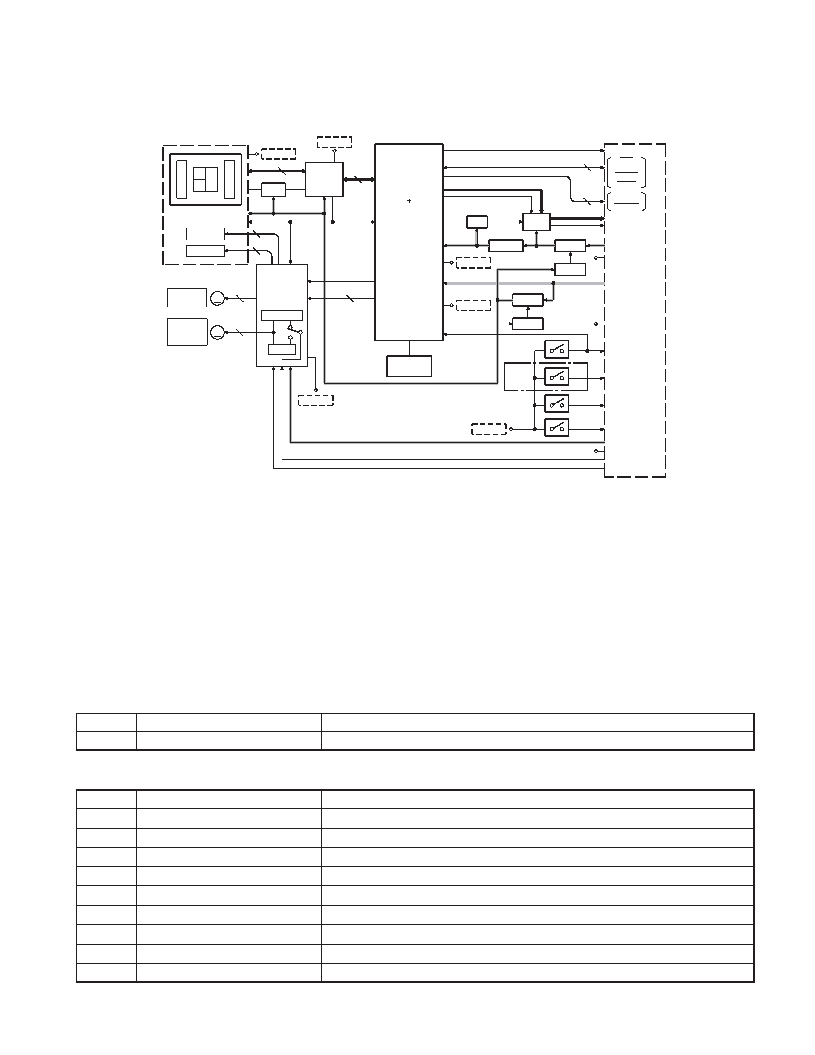
CD PLAYER UNIT (X32-5550-00)
Ref No.
Application / Functions
Operation / Condition / Compatibility
Generation of RF signal based on the signals from the APC circuit and pickup, and
IC1
RF amplifier adapted for CD-RW
generation of servo error (focusing error and tracking error) signals. Detection of dropout,
anti-shock, track crossing and off-track conditions, included gain control function during
CD-RW.
Focusing, tracking, sled and spindle servo processing. Automatic adjustment (focusing,
IC2
CD signal processor built-in MI-COM
tracking, gain, offset and balance) operations. Digital signal processing (DSP, PLL, sub-
codes, CIRC error correction, audio data Interpol ration) operations, and Microcomputer
function.
IC4
4CH BTL driver
Focus, Tracking coil, Feed and Spindle motor driver IC
IC6
LPF
Audio active LPF
Q1
APC
LD power control
Q2
Q3 SW
When P ON signal gose "H", Q2 is ON
Q3
A.8V SW
When P ON signal gose "H" (Q2 is ON), Q3 is ON
Q4
D.5V SW
When P ON signal gose "L" (Q5 is ON), Q4 is ON
Q5
Q4 SW (P-ON)
When P ON signal gose "H", Q5 is ON
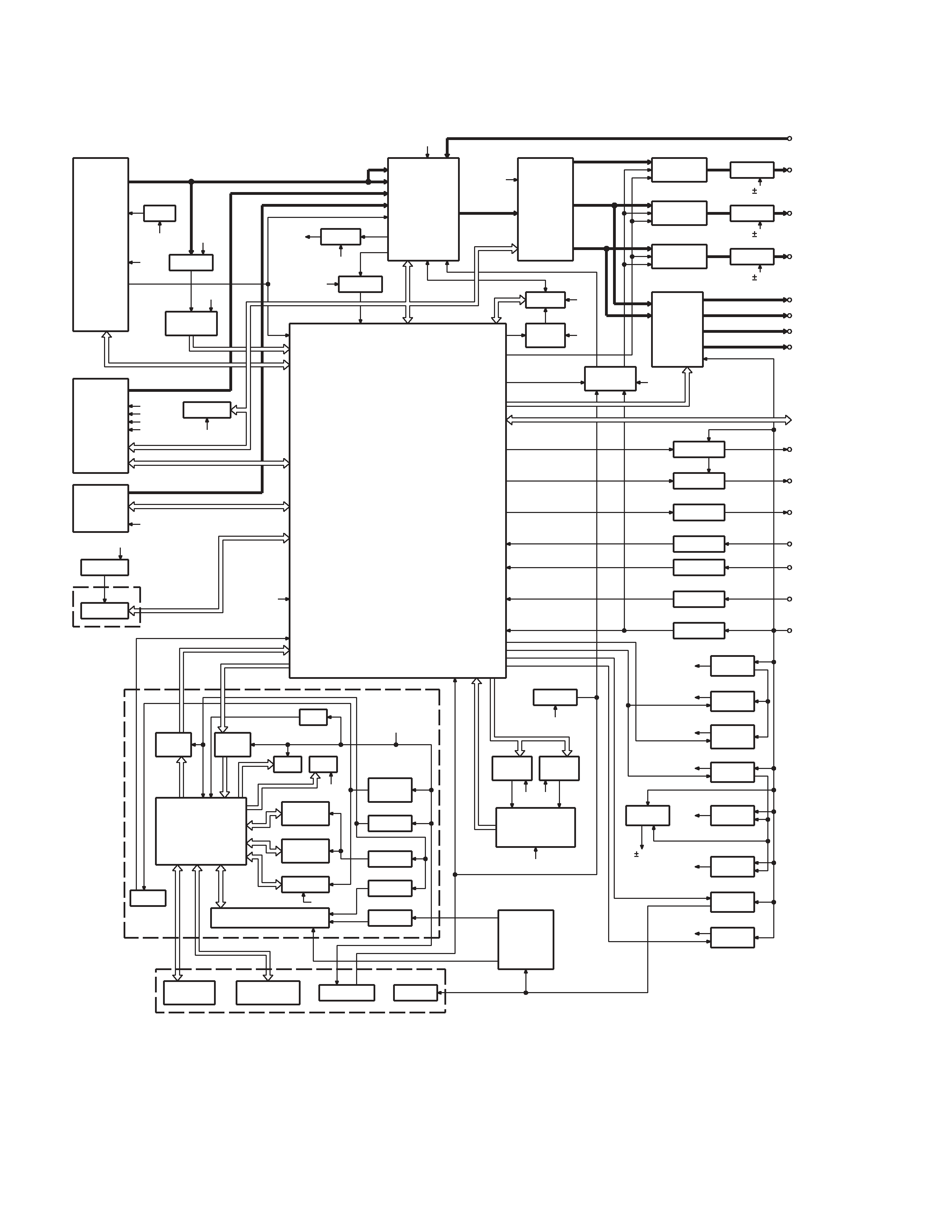
ELECTRIC UNIT (X34-3042-72)
Ref No.
Application / Functions
Operation / Condition / Compatibility
IC1
System control IC
System control microprocessor
IC2
E-VOL & tuner IC
E-VOL. FM/AM tuner & stereo decoder
IC3
Power supply IC
For A8V AVR
IC4
Audio power IC
Audio power amplifier
IC7
Reset IC
When BU5V line voltage is less than 3.5V, this IC output line is "L"
IC8
Muting logic IC
Control for MUTE, P-ANT & RESET muting
IC12
RDS decoder
Decode for RDS signal
IC13,14
Motor driver
Control for Panel mechanism motor
Q1,2
BU 5V AVR
While BU is applied when BU5V regulator output is +5V
Q3
SW5V AVR
When Q3base level goes L, SW5V regulator output is +5V
Q4,5
SW14V AVR
When Q5 base level goes H, SW14V regulator output is +14V
Q6~8
Audio 8V AVR
When Q6 base level goes H, A8V regulator output is +8.4V
Q9,34
Servo +B AVR
When Q34 base level goes H, S+B regulator output is +7.4V
Q11~14
Illumination +B AVR
When Q11 base level goes H, AVR output is +10.5V
Q25,26
P-CON SW
When Q26 base level goes H, P-CPN SW output is +14V
Q27,28
P-CON protection
Protect Q27 by turning on when P-CON output is grounded
Q29
Buffer
EX amp control buffer
Q30
Small lamp det. SW
When Q30 base level goes H, Q30 turned ON
COMPONENTS DESCRIPTION
background image
KDC-7027/7027Y
5
COMPONENTS DESCRIPTION
Ref No.
Application / Functions
Operation / Condition / Compatibility
Q32
BU detector
When Q32 base level goes H, Q32 turned ON
Q33
ACC detector
When Q33 base level goes H, Q33 turned ON
Q51,52
Muting driver
When base level goes L, muting driver is turned ON
Q55,56,59,60
Pre-out muting SW
When base level goes H, Pre-output is muted
Q63
E2P 5V SW
When Q63 base level goes L, E2P 5V is out for E2P ROM
Q102,103
AM +B SW
When Q102 base level goes H, AM +B is out to tuner unit
Q104
Buffer
Composite signal buffer for RDS
SYSTEM MICROPROCESSOR : UPD703030GC043 (X34-304 : IC1)
Pin No.
Pin Name
I/O
Description / Processing Operation
Fig.
1
PLL DATA
I/O
Data input/output terminal for Tuner front-end
2
AM+B
I/O
AM+B (AM operation : H)
3
(FM+B)
O
FM+B (FM operation : H, Last FM : H with RDS,RBDS model)
4PAN E2P DATA
I/O
Variable illumination D/A converter, E2PROM DATA terminal
5PAN E2P CLK
I/O
Variable illumination D/A converter, E2PROM CLK terminal
6
EVDD
-
VDD 5V
7
EVSS
-
GND
8
AFS
O
Time constant switching for noise detection (FM seek, AF search, AUTO 0 : L, Receiving : H)
9
BEEP
O
BEEP audio output terminal
10
REMO
I
Remote control input terminal
11
P MUTE
O
Audio power IC muting control terminal (POWER OFF, ALL OFF, TEL MUTE : L)
12
SVR
O
Audio power IC SVR discharge circuit control terminal
13
IC2 SDA
I/O
CD mechanism, IC2, IC5, ROM correction DATA line
14
IC2 CLK
I/O
CD mechanism, IC2, IC5, ROM correction CLOCK line
15
P STBY
O
Audio power IC Stand-by terminal (POWER IC ON, ALL OFF : H, POWER IC OFF : L)
16
P CON
I/O
Power control terminal (POWER ON : H, POWER OFF, ALL OFF : Hi-Z)
17
DIMMER CONT
O
Dimmer control terminal (W-LED only : Pulse control F=1KHz, Normal : H)
18
TEST
-
NC (GND)
19
TYPE2
I
Destination select terminal
20
MUTE
O
MUTE output terminal (ON : OPEN, OFF : L)
21
PRE MUTER
O
PREOUT (Rch) muting control terminal
22
PRE MUTEL
O
PREOUT (Lch) muting control terminal
23
BU DET
I
Momentary power dropped detection terminal (No Backup, Momentary power dropped : H, Backup : L)
24
ACC DET
I
ACC detection terminal (With ACC : L, Without ACC : H)
25
SW5V
I/O
SW5V control terminal (OFF : H, ON : L)
26
EXT AMP CONT
O
External amplifier control terminal
MICROCOMPUTER'S TERMINAL DESCRIPTION

Reviews

There are no reviews of this manual yet.