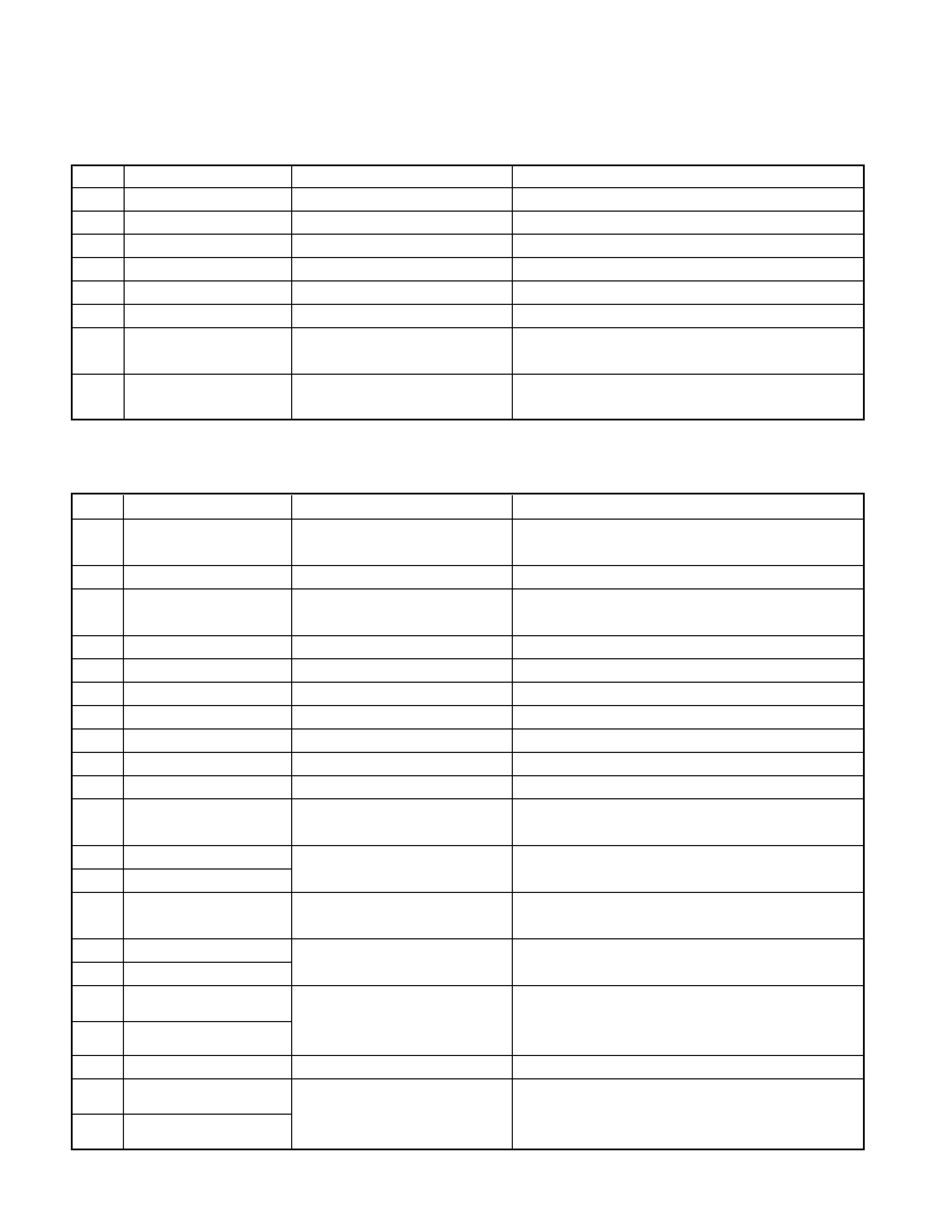
KENWOOD KDC-5090B Service Manual

Cover page of KENWOOD KDC-5090B Service Manual

Service Manual for KENWOOD KDC-5090B, downloadable as a PDF file.

We also have owner's manual to this model.

Manual details

  • Immediate download after payment.
  • Delivered as a PDF file.
  • The manual has 27 pages
  • File size: 1.68 MB
  • Available language versions: English
  • Different language versions may vary sligthly in file size and page count.

We guarantee that...

  • our manuals are complete,
  • the manual includes circuit diagrams,
  • our manuals are checked with antivirus,
  • We'll issue refund if the manual is damaged, incomplete or unreadable (our refund policy)

Sample pages

Thumbnail of page 1Thumbnail of page 2Thumbnail of page 3Thumbnail of page 4
Thumbnail of page 5Thumbnail of page 6Thumbnail of page 7Thumbnail of page 8
Thumbnail of page 9
background image
© 2001-11 PRINTED IN JAPAN
B51-7870-00 (N) 1940
CD RECEIVER
KDC-5090B/BY
SERVICE MANUAL
47W 4
X
KDC-5090B
DAB
PTY
TI
VOL ADJ
The MECHANISM OPERATION DESCRIPTION is the same as model KDC-S3007 and KDC-5050RG.
Please refer to the service manual for model KDC-S3007(B51-7029-00) or KDC-5050RG(B51-7099-00).
DC cord
(E30-4944-05): KDC-5090BY
(E30-4958-05): KDC-5090B
Antenna adaptor
(T90-0523/0534-05)
Screw set
(N99-1704-05)
Lever
(D10-4562-04)x2
(D10-4621-04)x2 : KDC-5090B
Mounting hardware assy
(J21-9641-13)
Plastic cabinet assy
(A02-1497-13)
Escutcheon assy
(B07-3007-03)
Front glass
(B10-4236-11)
Panel assy
(A64-2683-12)
background image
KDC-5090B/BY
2
CONTENTS
BLOCK DIAGRAM ................................................................... 3
COMPONENT DESCRIPTION ................................................ 4
MICROCOMPUTER'S TERMINAL DESCRIPTION ................. 6
TEST MODE ............................................................................ 8
ATTENTION ........................................................................... 10
PC BOARD ............................................................................. 11
CD PLAYER UNIT (X32-5010-00) ....................................... 11
ELECTRIC UNIT (X25-87X2-7X) ....................................... 13
SWITCH UNIT (X13-99XX-X4) ........................................... 14
SCHEMATIC DIAGRAM......................................................... 17
ELECTRIC UNIT (X25-87X2-7X) ....................................... 17
SWITCH UNIT (X13-99XX-X4) ........................................... 21
CD PLAYER UNIT (X32-5010-00) ...................................... 23
EXPLODED VIEW ................................................................. 25
PARTS LIST ........................................................................... 27
SPECIFICATIONS............................................... BACK COVER
background image
KDC-5090B/BY
3
BLOCK
DIAGRAM
PLL+B
FM+B
Q45,47
Q46,48
AM+B
DIMMER
MUTE
2WAY
DET.
ACC
BU DET.
A8V
A8V
Q14,15
Q16,17
Q19-22
SERVO AVR
Q18
SERVO+B
SW5V
Q13
Q55,56
Q33
Q11,12
SW5V
BU5V
BU5V
P CON
Q27,29
Q30,32
MUTE
IC3
Q7
DRIVER
MUTE
Q1,2,5,6
POWER IC
IC4
u-COM
CD
CH
F/E
A1
E-VOL
IC2
PRE OUT
SP-OUT
DIMMER
TEL-MUTE
ACC
ANT-CONT
P-CONT
DECODER
RDS
IC1
IC7
Q51
ILLUM
+B
BUFFER
NOISE
Q43
PRE OUT OUTPUT VOLTAGE
Q26
Q34
NAVI-MUTE
PANEL 5V
PANEL 5V
SW14V
PANEL
POSITION
DET.
CH
QUAL
SERVO+B
MUTE R
STOP
SW2
LO/EJ
MUTE L
RST
SW3
SW1
SDA
SCL
A8V
BU5V
SW5V
RST
REQ C
CLK
CH-CON
DATA H
REQ H
CD
AM
FM
P MUTE
MUTE
SW5V
PANEL5V
ILL+B
SR
T
-SW1
SR
T
-SW2
RDCK
RDDA
QUAL
SDA
SCL
AFS
AFS
A8V
PLL DATA
PLL CLK
IFC OUT
S-METER
SW5V
DATA C
BACK UP
BU5V
CHANGER
AM
FM
230mV
1200mV
1200mV
251mV
AUDIO OUT
FM+B
NOISE
CD
MODEL
3600mV
3600mV
855mV
1372mV
LEVEL
MO SW
BACK UP
BU5V
RESET IC
IC8
MATRIX
KEY
L DATAL
L CE
L CLK/PANEL
DIMMER
REMO
PAN5V
RESET
DRIVER
MUTE
LCD DRIVER
IC1
IC2
Q5
Q55,56
Q3,4
ED1
SW
RESET
LCD
(BACK LIGHT WLED)
DIMMER
PWM CONTROL
REMO
G/R SW
LCD AVR
PANEL 5V
(X13- )
,42
PAN 5V
SW
background image
KDC-5090B/BY
4
Ref. No.
Component Name
Application / Function
Operation / Condition / Compatibility
IC1
LC75808W
LCD driver with the key matrix
IC2
RS-171
Remote sensor IC
Q1
DTA114EUA or KRA302
Key-permission SW
For the key scanning start
Q3
2SD2114K
Red LED SW
When a base goes Hi, RED LEDs are turned on.
Q4
2SD2114K
Green LED SW
When a base goes Hi, GREEN LEDs are turned on.
Q5
2SC2412K or 2SD601A
VLCD AVR
Q6
DTA114EUA or KRA302
REMO SW
While a base goes Lo, PAN 5V is supplied to the Remote
sensor IC.
Q7
DTC143ZK
Dimmer SW
Usually Q7's base goes Hi. When DIMMER mode is
selected, pulse wave shape is applied to Q7's base.
q ELECTRIC UNIT (X25-87X2-7X)
Ref. No.
Component Name
Application / Function
Operation / Condition / Compatibility
IC1
UPD703033GC117
System MI-COM.
or UPD703033GC145
IC2
TDA7407D
E.VOL & N.C.MPX IC
IC3
HD74HC02FP
Mute logic
2-input NOR x 4
or TC74HC02AF
IC4
TA8263BH
Power AMP. IC
IC7
TDA7479D
RDS decoder
IC8
S-80837ANNP
Reset IC
When BU 5V voltage is less than 3.7V, IC outputs Lo.
Q1
DTC143TUA or KRC410
Pre mute (Front L)
When Q1's base goes Hi, Pre-output is muted.
Q2
DTC143TUA or KRC410
Pre mute (Front R)
When Q2's base goes Hi, Pre-output is muted.
Q5
DTC143TUA or KRC410
Pre mute (Rear L)
When Q5's base goes Hi, Pre-output is muted.
Q6
DTC143TUA or KRC410
Pre mute (Rear R)
When Q6's base goes Hi, Pre-output is muted.
Q7
DTA124EUA or KRA303
Mute driver
When BU detection SW or System RESET or MI-COM.'s
Pre-mute is working, a base goes Lo, and Q7 is turned on.
Q11
2SC4081 or 2SD1819A
BU 5V AVR
While BACKUP is applied, AVR outputs +5V.
Q12
2SB1548(P)
Q11 and Q12 are inverted Darlington connection.
Q13
2SA1576A or 2SB1218A
SW 5V
While a base goes Lo, SW 5V is supplied to the
microprocessor peripheral circuits.
Q14
2SC4081 or 2SD1819A
A8V AVR
When Q14's base goes Hi, A8V AVR outputs 8V.
Q15
2SB1548(P)
Q16
DTC124EUA or UN5212
A8V AVR and SERVO +B AVR ON/OFF control
Q17
DTA124EUA or KRA303
SW14V SW
While Q16's base goes Hi, Q17 is turned on, A8V AVR and
SERVO +B AVR are working.
Q18
2SD2375
SERVO +B AVR
When Q18's base goes Hi, SERVO +B AVR outputs 8V.
Q19
DTC124EUA or UN5212
ILL +B AVR ON/OFF control
Q20
DTA124EUA or KRA303
ILL +B SW
While Q19's base goes Hi, Q20 is turned on, and ILL +B
AVR is working.
COMPONENT DESCRIPTION
q SWITCH UNIT (X13-99XX-X4)
background image
KDC-5090B/BY
5
Ref. No.
Component Name
Application / Function
Operation / Condition / Compatibility
Q21
2SB1184
ILL +B AVR
While Q22's base goes Hi, AVR outputs +10.5V.
Q22
2SC4081 or 2SD1819A
Works during POWER ON mode with a panel attached to the set.
Q26
DTC144EUA or UN5213
Small lamp detection SW
When vehicle small lamps turn on, Q26 is turned on .
Q27
DTC114YUA or UN5214
P-CON SW
When Q27's base goes Hi, Q32 is turned on .
Q32
2SB1277(Q,R)
Works during POWER ON mode.
Q29
DTA124EUA or KRA303
P-CON. protection inhibit SW
Prevents Q30 tuning ON during start-up after power ON.
Q30
2SA1576A or 2SB1218A
P-CON. protection SW
Protect Q32 by turning ON when P-CON output is grounded.
While BACKUP is applied, a base goes Hi, and Q33 is
Q33
2SC4081 or 2SD1819A
BU detection SW
turned on. When momentary power down has detected,
a base goes Lo, and Q33 is turned off.
Q34
2SC4081 or 2SD1819A
ACC detection SW
While ACC is applied, a base goes Hi, and Q34 is turned on.
Q42
DTC124EUA or UN5212
E. VOL mute SW
When BU detection SW or MI-COM.'s mute is working,
a base goes Hi, and Q42 is turned on.
Q43
2SC4081 or 2SD1819A
Noise buffer
Q45
DTC124EUA or UN5212
FM +B SW
When Q45's base goes Hi, Q47 is turned on.
Q47
2SB1277(Q,R)
Works during FM reception mode.
Q46
DTC124EUA or UN5212
AM +B SW
When Q46's base goes Hi, Q48 is turned on.
Q48
2SB1277(Q,R)
Works during AM reception mode.
Q51
DTC144EUA or UN5213
IFC buffer
Waveform shaping
Q52
2SC4081 or 2SD1819A
Composite signal output buffer
Q55
2SA1576A or 2SB1218A
PAN 5V SW
While a panel is attached to the set, Q56's base goes Hi,
Q56
DTC124EUA or UN5212
and Q55 is turned on.
q CD PLAYER UNIT (X32-5010-00)
Ref. No.
Component Name
Application / Function
Operation / Condition / Compatibility
Generation of RF signal based on the signals from the APC
circuit and pickup, and generation of servo error (focusing
IC1
AN22000AA
RF amplifier
error and tracking error) signals.
Detection of dropout, anti-shock, track crossing and off-track
conditions, Gain control function building in.
IC2
MN662774KG1
CD signal processor bult-in MI-COM.
IC4
BA5917AFP
4CH BTL driver
Focusing coil, tracking coil, spindle motor and sled motor driver
IC6
NJM4565MD
OP Amp.
Low pass filter
Q1
MCH6101
APC
LD power control
Q2
DTC124EUA
P ON SW
When CD source is selected, Q2's base goes Hi, Q3 and
Q4 are turned on.
Q3
DTA143XUA
A.8V SW
A8V ON/OFF control. When a base goes Lo, Q3 is turnde on.
Q4
2SA1362 (Y)
D.5V SW
D5V ON/OFF control. When a base goes Lo, Q4 is turnde on.
Q5
DTC124EUA
MOTOR SW
When CD loading or eject operation is activating, Q5's base
goes Hi, Q4 is turned on.
COMPONENT DESCRIPTION

Reviews

There are no reviews of this manual yet.