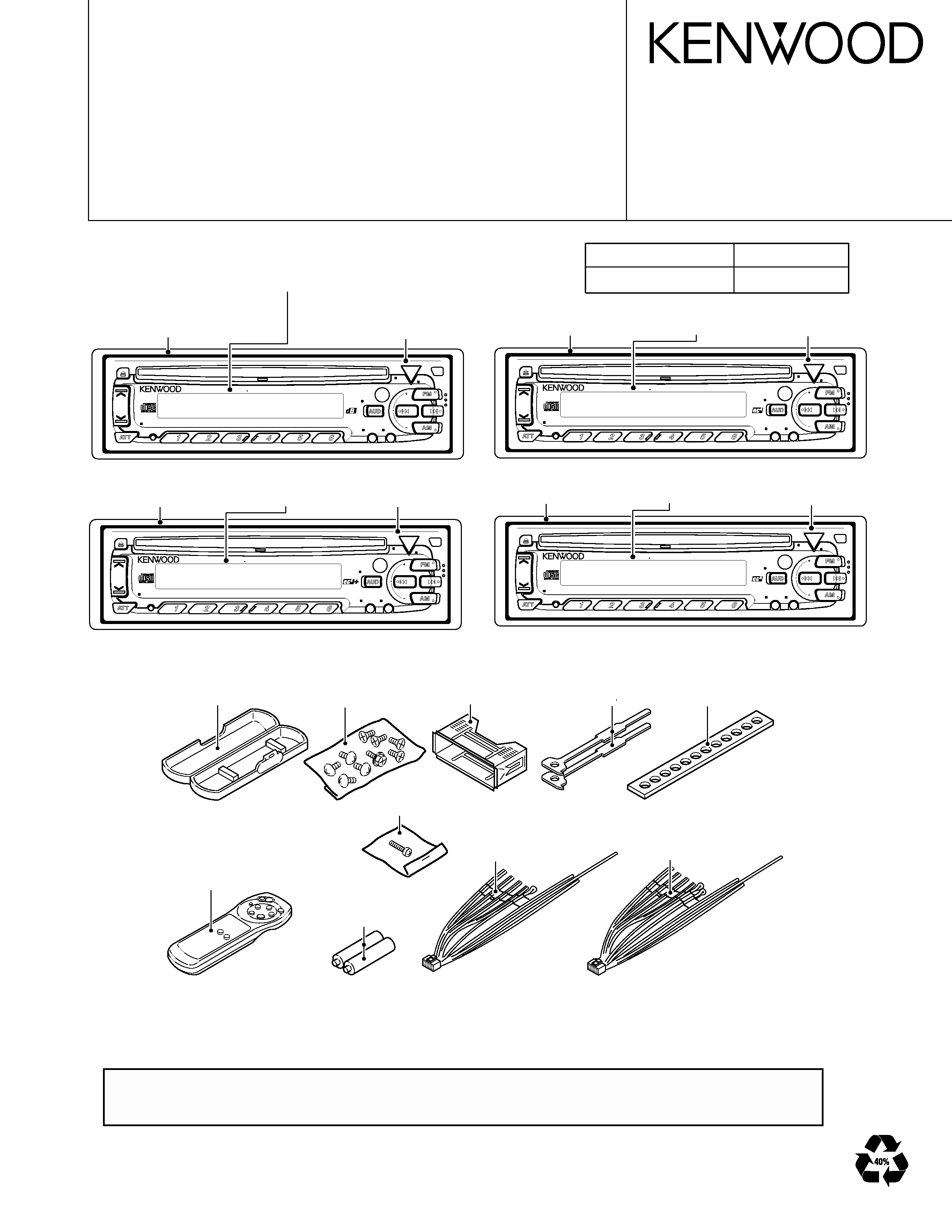
KDC-315S/V/415S
4015/4016/CG
3
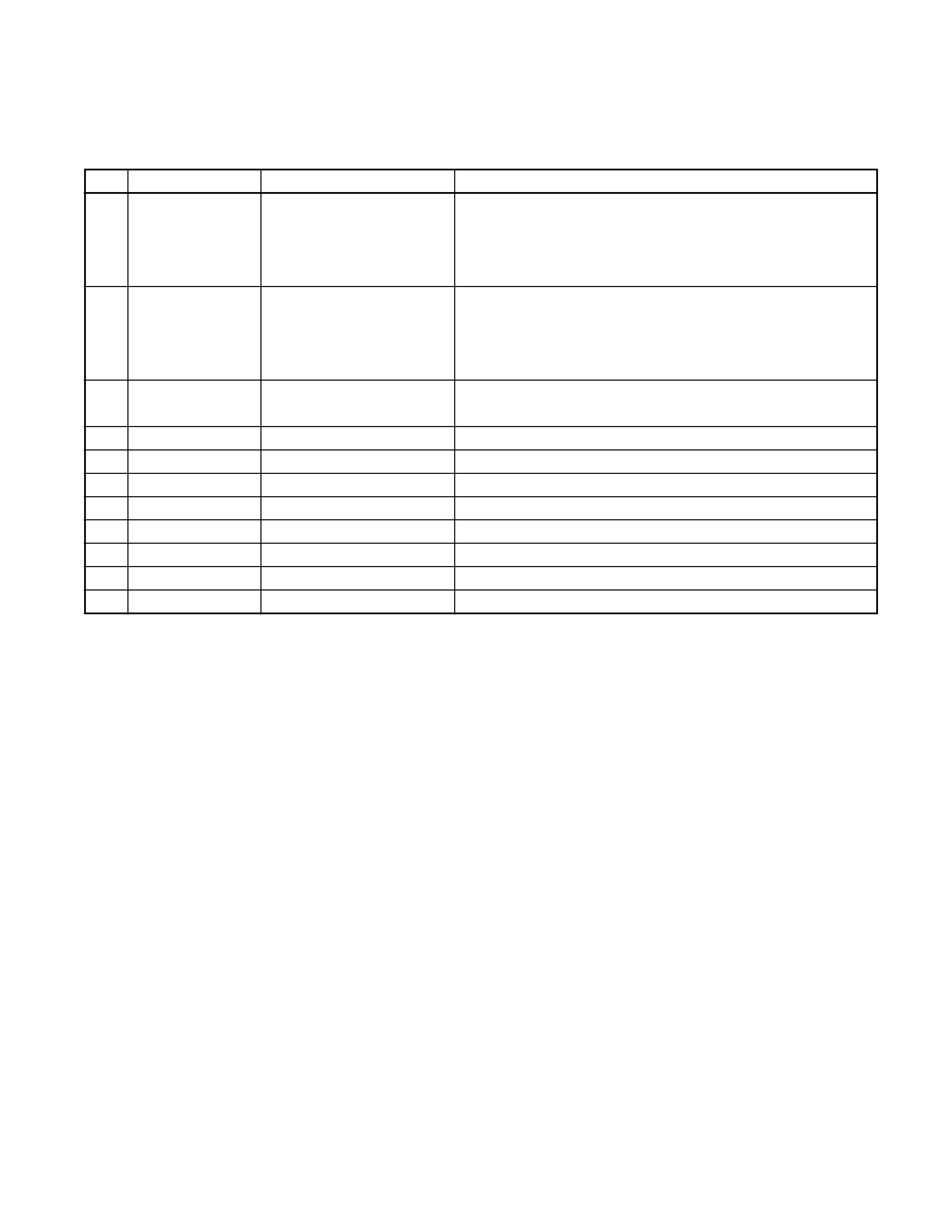
COMPONENT DESCRIPTION
SWITCH UNIT(X13-9680-1X)
Ref.No. Component Name
Application/Function
Operation/Condition/Compatibility
IC1
LC75853NE
LCD driver with key-matrix
IC2
RS-171
Remote control light sensor
Q1
DTA114EKorUN2111 key-matrix permission SW
Ready on key-matrix
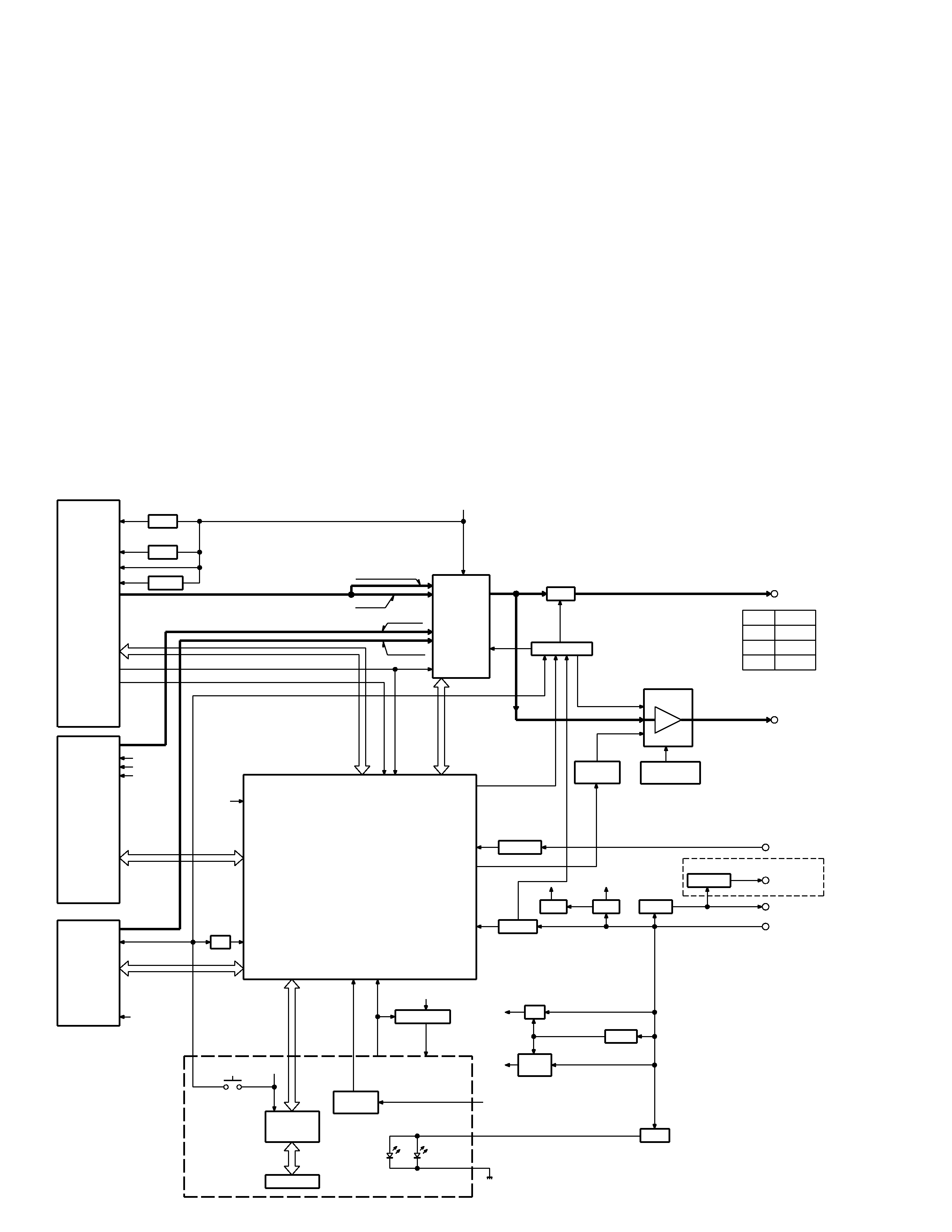
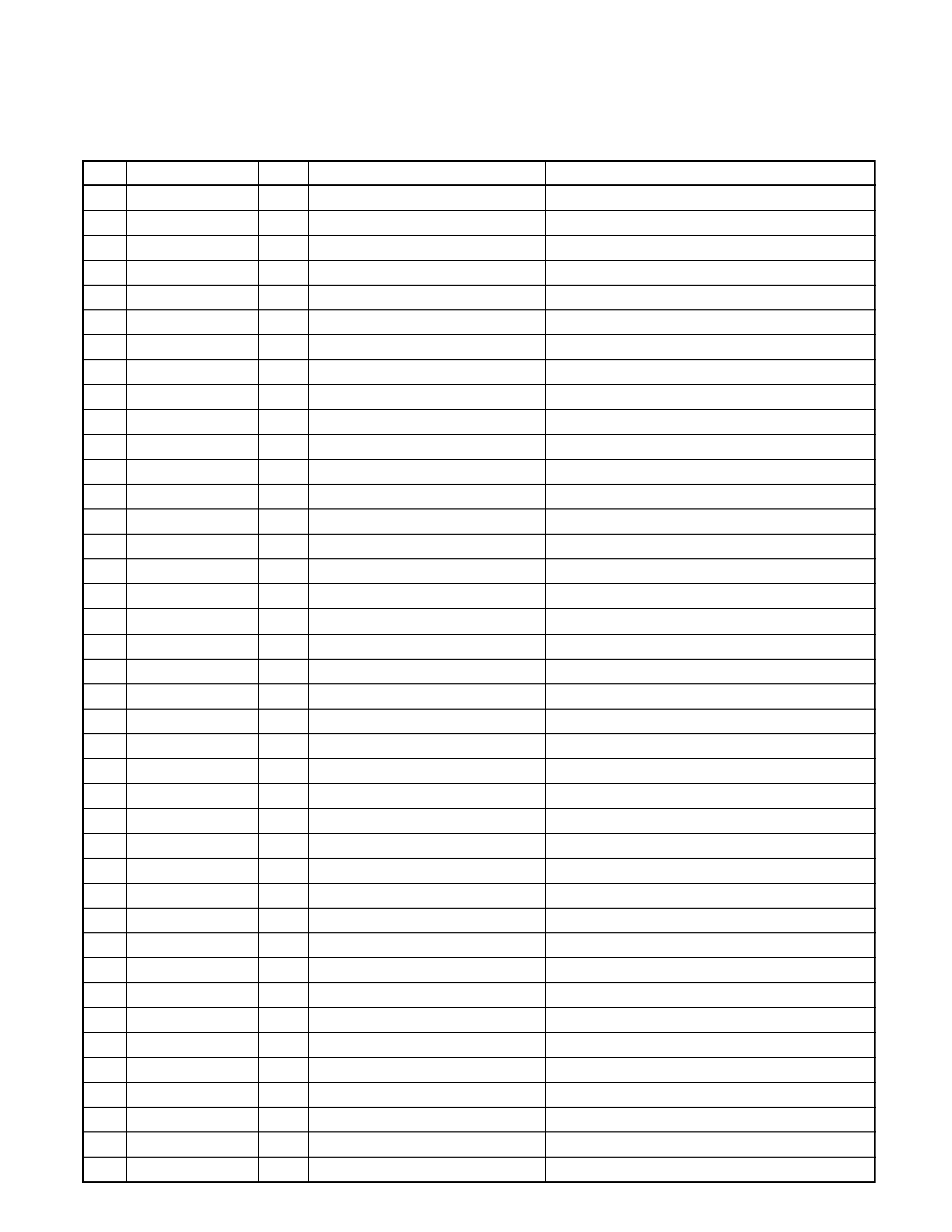
ELECTRIC UNIT(X25-8430-XX)
Ref.No. Component Name
Application/Function
Operation/Condition/Compatibility
IC1
UPD780058GC144 System MI-COM.
IC2
TDA7400D
E-VOL. & N.C. MPX
IC3
PST9130NR
Reset IC
"Lo": Detection voltage below 3.0V
IC4
TDA7386
Power IC
IC5
HD74HC27FP
Mute logic
3 input NOR gate x3
Q1
2SB1565F(E,F)
BU 5V AVR
Inverted darlington connection
Q2
2SC1740S
ON during BU applied
Q3
DTA124EKorUN2112
SW14V
Audio 8V AVR and Servo AVR ON/OFF control
Q4
DTC144EKorUN2213
Q3 is turned ON when Q4's base goes "Hi".
Q5
2SB1184
Audio 8V AVR
Q5 is turned ON when Q6's base goes "Hi".
Q6
2SC1740S
Inverted darlington connection
Q7
2SD2396F40
Servo AVR
ON when the base goes "Hi".
Q8
DTC144EKorUN2213
Q9
DTA124EKorUN2112
Illumination AVR
Q10 is turned ON when Q8's base goes "Hi".
Q10
2SB1184
Q11
2SC1740S
Q12
2SC1740S
BU detection(Momentary power down detection)
ON when the base goes "Hi" during BU applied.
Q13
2SC1740S
ACC detection
ON when the base goes "Hi" during ACC applied.
Q14
2SA1036K
SW 5V
ON when the base goes "Lo".
Q15
2SB1277(Q,R)
P-ANT SW
Q15 is turned ON when Q16's base goes "Hi".
Q16
DTC114YKorUN2214
ON during FM/AM reception
Q17
2SB1277(Q,R)
P-CON SW
Q17 is turned ON when Q20's base goes "Hi".
Q20
DTC114YKorUN2214
ON while power is on or CD loading/eject.
Q18
2SA1037K
P-CON protection
Protect Q17 by turning ON when P-CON output is grounded.
Q19
DTA124EKorUN2112
Prevents Q18 tuning ON during start-up after power ON.
Q50
DTC144EKorUN2213 RESET SW
System RESET is activated when the panel reset SW is pressed.
Q150 DTC114YKorUN2214 SVR SW
POWER IC RESET is activated when the base goes "Hi".
Q151 DTC143TKorUN2216
Q152 DTC143TKorUN2216
Audio mute SW
Audio pre-outs are muted when the base goes "Hi".
Q153 DTC143TKorUN2216
Q154 DTC143TKorUN2216
Q155 DTA124EKorUN2112 Mute driver for Audio mute SW
ON when the base goes "Lo".
Q156 DTC144EKorUN2213 E-VOL. mute SW
E-VOL. is muted when the base goes "Hi".
Q200 2SB1277(Q,R)
FM+B SW
Q200 is turned ON when Q201's base goes "Hi".
Q201 DTC124EKorUN2212
ON during FM reception
Q202 2SB1277(Q,R)
AM+B SW
Q202 is turned ON when Q203's base goes "Hi".
Q203 DTC124EKorUN2212
ON during AM reception
Q207 2SA1037K
Panel detection SW
ON when the base goes "Lo" during the panel closed.