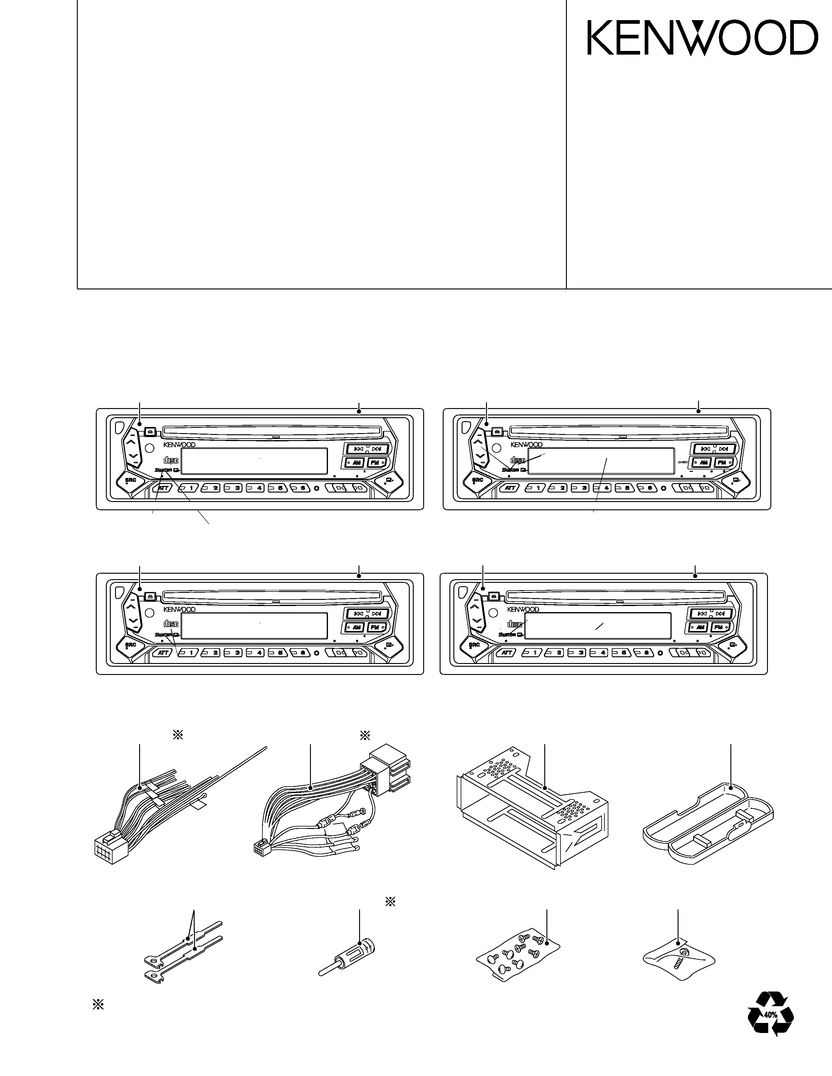
KDC-2023, 2024A/SG/SYA/SYG, 2094YA/YG, 222/S,3023
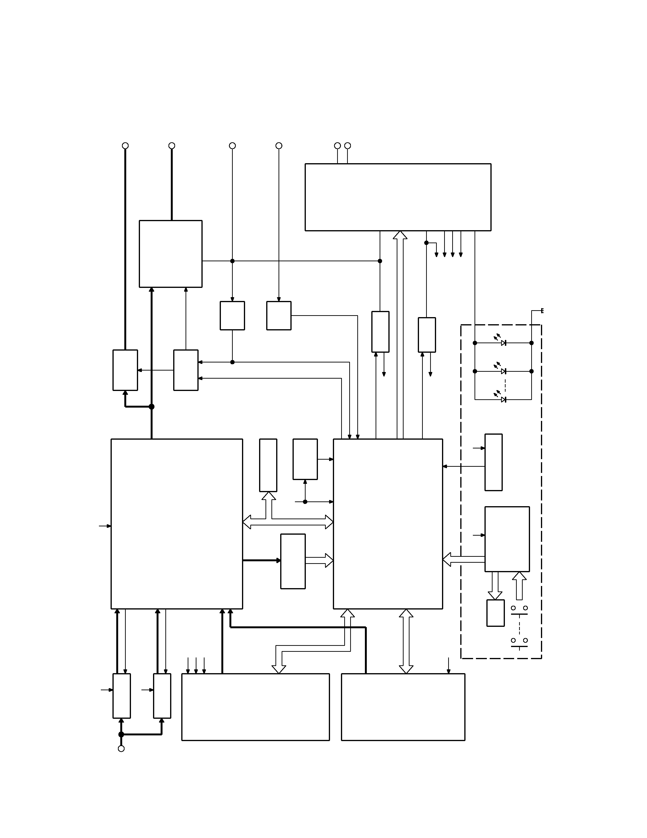
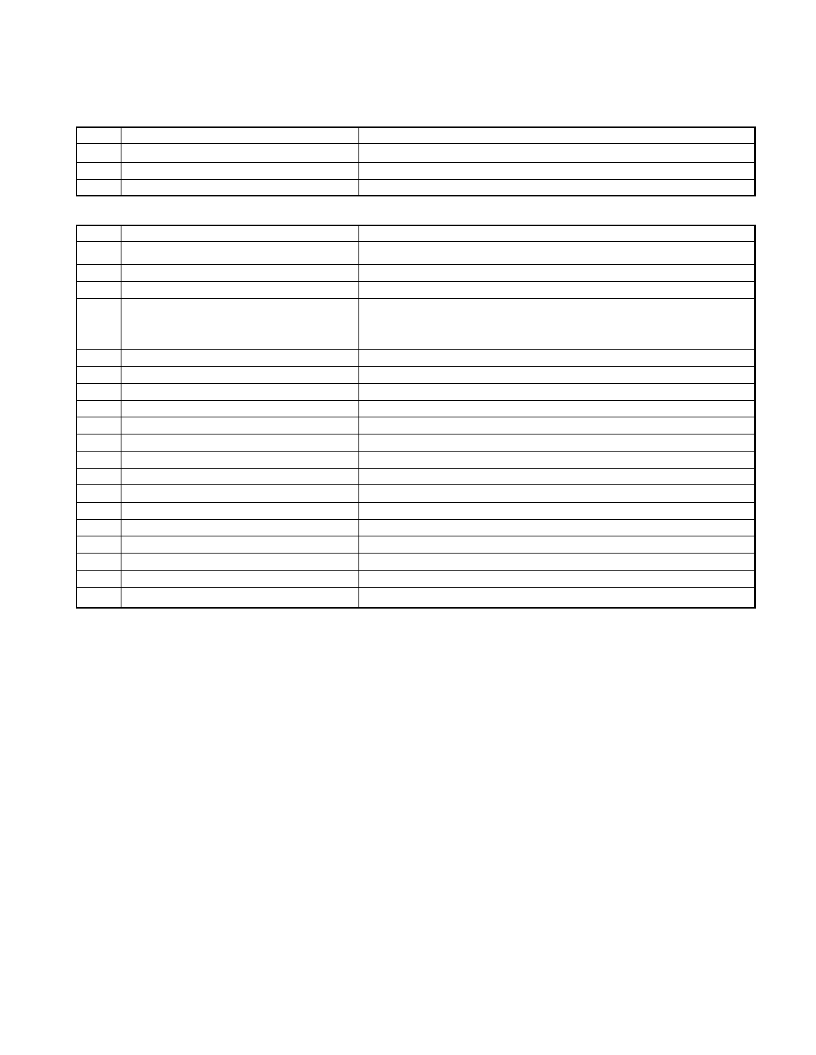
MICROCOMPUTER'S TERMINAL DESCRIPTION
4
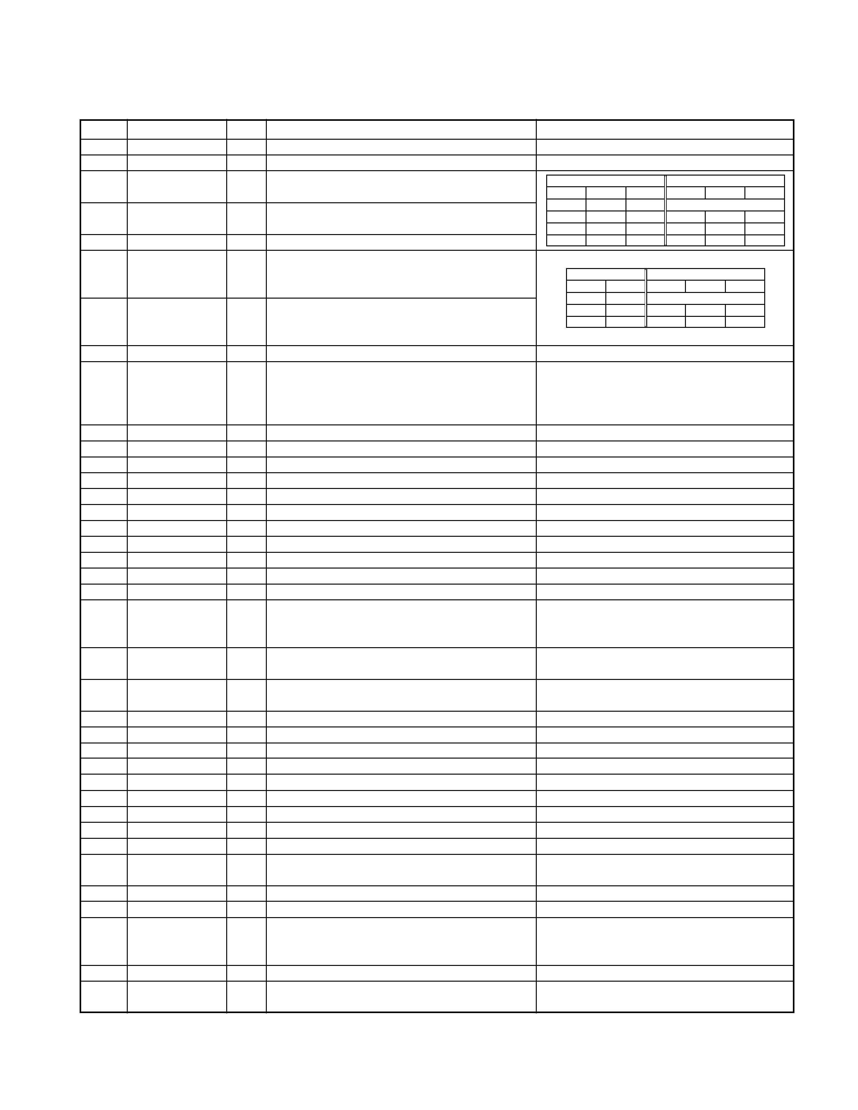
q SYSTEM MICROCOMPUTER uPD780058GCxxx (X25 : IC1)
Pin No.
Name
I/O
Description
Processing Operation
1
TDF DET
I
Panel detection
H:Panel detached L:Panel attached
2
8EJE SW
I
H:Eject is completed
Except 8cm CD model:always output L
3
NC
O
Not used (out put L)
4
Avss
H:Panel detached L:RESET
5
L-RST
O
LCD driver RESET
3 normal H , Power off L
When 7seg model,output L
6
L-CE
O
LCD driver selection
H:Select (panel communication)
When panel attached,output L
7
AVREF1
8
NC
Not used (connected to 9pin)
9
IC10-DATA
I/O
IC10,E2PROM data communication
3 non communication : H
10
IC10-CLK
O
IC10,E2PROM clock communication
3 non communication : H
Non communication : H
11
L-DATAL
I
Data input from the LCD driver
When panel detached : L
3 Pull down on X25 unit,Pull up on X16 unit
12
L-DATAS
O
Data output to the LCD driver
When panel detached , output L
13
L-CLK
O
Clock output to the LCD driver
When panel detached , output L
14
R-DATA
I
Data input from the RDS
Except RDS model : output L
15
R-QUAL
I
Quality input from the RDS
Except RDS model : output L
16
CH-DATAC
I
Data input from the changer (new 5L)
Except changer model : output L
17
CH-DATAH
O
Data output to the changer (new 5L)
When non communication ,last data keeping
Except changer model : output L
18
CH-CLK
I/O
Clock input/output with the Changer (new 5L)
Check the old and new
Except changer model : output L
19
CH-REQH
O
Request output to the changer (new 5L)
L:Requset
Except changer model : output L
20
NC
O
Not used (output L)
21
AFS
O
Noise detection time constant switching terminal
H:Normal L:FM/AM seek and AF search
3 (When tuner SRC auto zero , L)
22-24
NC
O
Not used (output L)
25
CH-CONT
O
Changer control
H:Changer on L:Changer off
Except changer model : output L
26
TYPE REF
O
5V lines output for destination setting
H:During destination reading
27
SD
I
Tuner SD input
H:Station detected
28
NC
O
Not used (output L)
29
TYPE2
I
Destination type selection terminal 2
Refer to destination type list.
30
TYPE1
I
Destination type selection terminal 1
Refer to destination type list.
31
TYPE0
I
Destination type selection terminal 0
Refer to destination type list.
32
TUNER-TYPE1
I
Destination available/genuine model rool off
H:genuine model 1 L:available model
33
Vss1
34
TUNER-TYPE0
I
Destination available/genuine model noise cancel H:genuine model 0 L:available model
35
MUTE
O
Mute (E.Vol,Preset) control
H:mute on L:mute off
Power off after that 15 second L
36
M-DATA
I/O
Data input/output with the CD mechanism
3 non communication : H
37
M-CLK
O
Clock output to the CD mechanism
3 non communication : H
When adjustment = H
38
ADJ
O
Tuner lines adjustment
PS1-0,1=L
PS1-2,2-0,1=Hi-z
IC10-DATA,CLK=Hi-z
39
P-MUTE
O
Power IC mute control
H:mute off L:mute on
Power off after that 15 second H
40
SVR
O
Power IC servo control
H:When momentary power down detected
L:Nomal
41
P-STBY
O
Power IC standby control
H:Power IC ON L:Power IC OFF
42
SW5V
O
SW 5V control
H:SW5V OFF L:SW5V ON
Power off after that 10 second H