KENWOOD KCA-S210A Owner's Manual

Cover page of KENWOOD KCA-S210A Owner's Manual

Owner's Manual for KENWOOD KCA-S210A, downloadable as a PDF file.

Manual details

  • Immediate download after payment.
  • Delivered as a PDF file.
  • The manual has 44 pages
  • File size: 1.24 MB
  • Available language versions: Japanese, Portuguese, French, English, Spanish, Dutch, German, Italian
  • Different language versions may vary sligthly in file size and page count.

We guarantee that...

  • our manuals are complete,
  • our manuals are checked with antivirus,
  • We'll issue refund if the manual is damaged, incomplete or unreadable (our refund policy)

Sample pages

Thumbnail of page 1Thumbnail of page 2Thumbnail of page 3Thumbnail of page 4
Thumbnail of page 5Thumbnail of page 6Thumbnail of page 7Thumbnail of page 8
Thumbnail of page 9
background image
KCA-S210A
CD / MD CHANGER SWITCHING UNIT WITH AUXILIARY RCA STEREO INPUT
3 page 2-7
INSTRUCTION MANUAL
UNITE DE COMMUTAION DU CHANGEUR CD/MD AVEC
ENREE STEREO RCA AUXILIAIRE
3Page 8-13
MODE D'EMPLOI
BEDIENUNGSANLEITUNG
©PRINTED IN JAPAN B64-1414-00 (W) (DT)
ISTRUZIONI PER L'USO
GEBRUIKSAANWIJZING
MANUAL DE INSTRUCCIONES
MANUAL DE INSTRUÇÕES
SCHAKELEENHEID VOOR DE CD / MD WISSELAAR MET
EXTRA CINCH STEREO INGANG
3Page 20-25
CD-/MD-WECHSLER-SCHALTGERÄT MIT ZUSÄTZLICHEM
RCA-STEREO-EINGANG
3Page 14-19
UNITÀ DI COMMUTAZIONE DEL MULTILETTORE CD / MD
CON INGRESSO STEREO RCA AUSILIARIO
3Page 26-31
UNIDAD CAMBIADORA DE CAMBIADORES CDs/MDs CON
ENTRADA AUXILIAR ESTÉREO RCA
3Page 32-37
UNIDADE DE COMUTAÇÃO DO CARREGADOR CD / MD COM
ENTRADA AUXILIAR RCA ESTÉREO
3Page 38-43
background image
2-English
Connection
CHANGER 2
TO
CHANGER 1
CHANGER 1
TO
CONTROLLER
TO
H/U
TO
SWITCH
AUX
OFF
ON
SWITCH
PROTOCOL
ON
IN
AUX
Connection cable3
Centre unit
Connection cable (supplied with the CD changer)
Connection cable (supplied with the MD changer)
CD changer
MD Changer
Switching unit1
(Front side)
If you connect a model which can switch between disc
changers 1 and 2 by the centre unit (Unit group B/C/D), the
controller2 must not be connected. If it is connected, the
disc changers may not work properly.
2CAUTION
· After connecting the equipment, press the reset button on the centre unit.
· The figure shows that one CD changer and one MD changer are connected. Two CD changers or two
MD changers may be connected.
·A disc player such as the KDC-D300 may be connected instead of the disc changer.
· If you wish to adjust the cable length in accordance with the installation location of the switching unit,
such as in the trunk space, the disc changer extension cable may be used instead of the connection
cable3.
IMPORTANT INFORMATION
This unit is NOT designed to be connected directly to a CD changer that was manufactured and
sold before 1994. If you plan to use such units, please read the following information carefully.
· To control KDC-C600/ KDC-C800/ KDC-601/ KDC-401
A CA-DS100 (sold separately as an optional accessory), along with the extension cord supplied with the
CD changer, are required.
· KDC-C200/ KDC-C300/ KDC-C301/ KDC-C400/ KDC-C100/ KDC-C302/ C205/ C705 and CD changer Manufactured by
Other Companies are not compatible with this Kenwood model.
FAILURE TO FOLLOW THESE INSTRUCTIONS MAY RESULT IN DAMAGE TO THIS UNIT AND/OR THE CD
CHANGER.
NOTE
1Switching unit.......................................1
2Controller (cord length: 5 m) ...............1
3Connection cable (2 m) ........................1
4Velcro strip ............................................2
5Self-tapping screw( 4 × 16 mm).........2
6Cable band ............................................1
7Double-sided adhesive tape ................1
Components
Controller2
TO
CONTROLLER
TO
H/U
TO
CHANGER 1
TO
CHANGER 2
Switching unit1
(Rear side)
Connection
To the external unit
AV
IN
background image
English
-3
CHANGER 2
TO
CHANGER 1
CHANGER 1
TO
CONTROLLER
TO
H/U
TO
SWITCH
AUX
OFF
ON
SWITCH
PROTOCOL
ON
IN
AUX
If you want to connect a stack CD changer
Connection cable (supplied with the stack CD changer)
Disc player
Stack CD changer
Extension cable (CA-C2E:Optional)
· Connect it to a centre unit belonging to Group C or Group D.
· Connect the stack CD changer to the terminal labelled TO CHANGER 2.
· The KDC-C810 cannot be connected.
· Up to two disc changers can be connected.
· The O-N switch on the disc changer and the disc player should be set to "N". If you set it to "O", the
equipment will not function correctly.
· The total length of the cable between the units should not be more than 13m.
· If the voltage is low and the internal temperature of the switching unit is low, switching may fail to work
properly in some cases.
· The AUX switch on the stack CD changer should be switched "OFF" before using the equipment. The
AUX terminal on the KCA-S210A switching unit is the one that should be used.
2CAUTION
TO
H/U
TO
CHANGER 1
TO
CHANGER 2
Connection cable (supplied with the Disc changer)
Connection cable3
Centre unit
Disc changer
Switching unit1
(Front side)
Switching unit1
(Rear side)
To the external units
Not more than 13m
Centre unit
KCA-S210A
Stack CD Changer
Disc Player
AV
IN
background image
Installation
4-English
Installing the switching unit with a
board in the trunk space
1. Install the switching unit with self-tapping
screws5 (
4 × 16 mm).
2. Bind the cables with cable band6.
Self tapping screw5
(
4 × 16 mm)
Switching unit1
Cable band6
Board etc.
thickness: 17mm or more
;;;;;
;;;;;
;;;;;
carpet
Velcro strips4
1. Remove the backing from the Velcro strips4 and
attach it to the bottom of the switching unit1.
Install the switching unit on the carpet.
2. Bind the cables with cable band6.
Installing the switching unit on the
carpet under a seat
· Install the switching unit1 in places that do not obstruct driving.
· Install the switching unit1 in places where it is not touched by the tip of the shoes of a rear seat
passenger.
· Do not install the unit in places where it is exposed to direct sunlight, high heat, or where water may
splash over it.
· Do not place anything on top of the switching unit 1.
2CAUTION
Installing the controller
Controller2
Double-sided
adhesive
tape7
1. Wipe off the installation location with a cleaning cloth.
· Install the controller2 on a flat surface. If it is
installed on a curved surface, the tape adhesion may
weaken and the controller may come off.
· Do not install the controller2 in places (such as on
the dashboard) where it is exposed to direct sunlight
and the temperature becomes high. Otherwise, the
controller2 will become deformed and unusable.
· Install the controller2 in places that do not obstruct
driving. Install the controller2 temporarily and verify
that the handle, shift knob, and side brake can be
operated smoothly.
2. Secure the controller2 in the specified place with the
double-sided adhesive tape7.
2CAUTION
Cable band6
Switching unit1
background image
English
-5
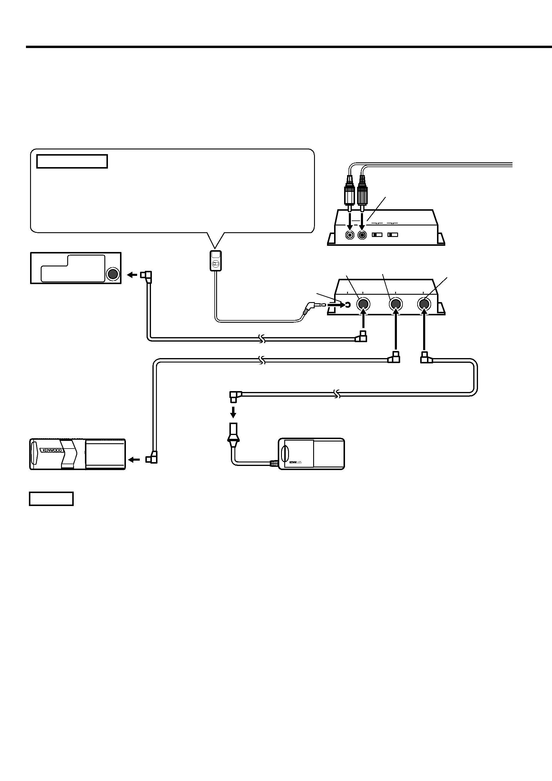
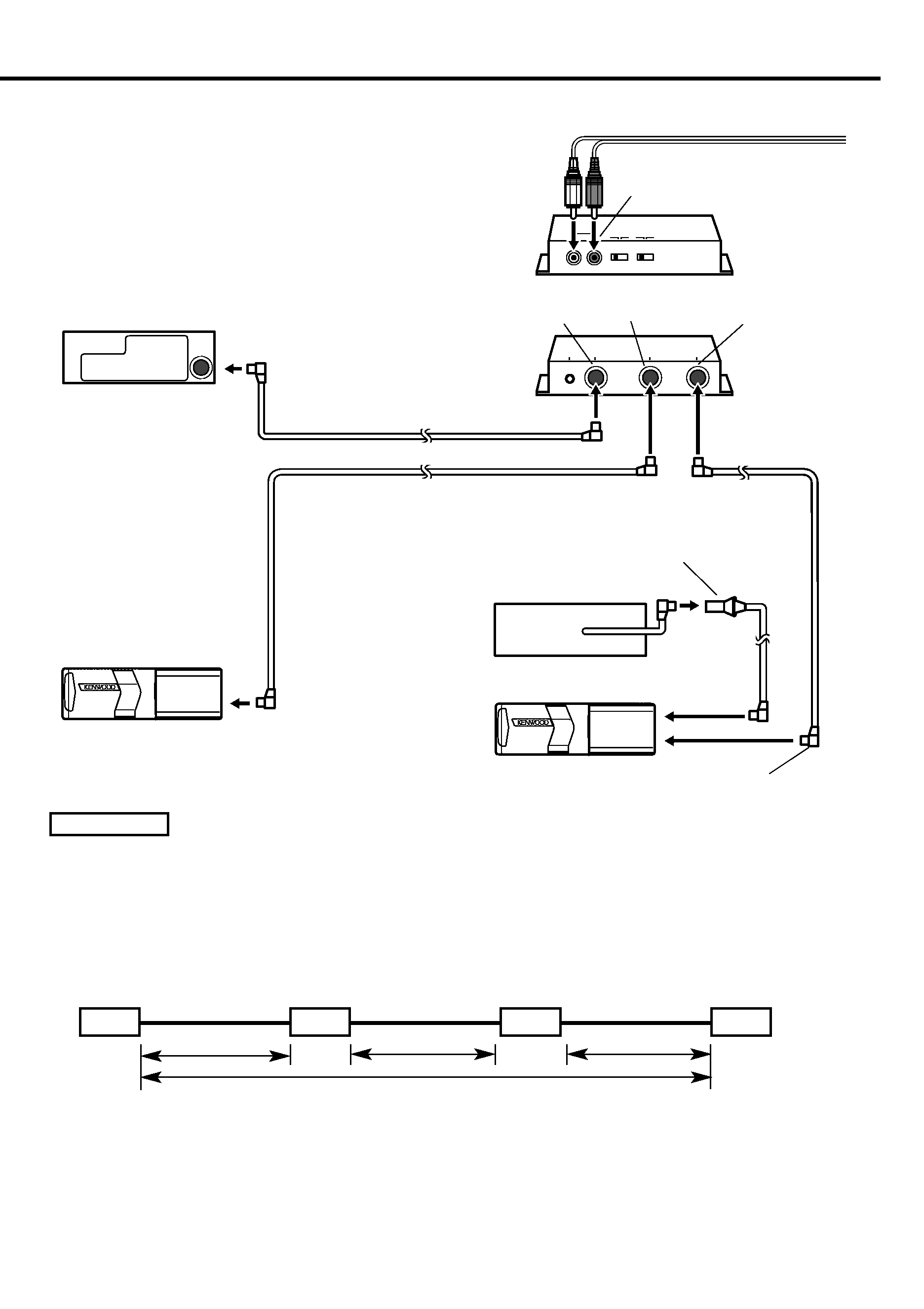
Identifying the type of centre unit you intend to connect
The setting of the PROTOCOL switch and the operation used to switch to AUX sound will
differ depending on the type of centre unit (cassette receiver, CD receiver, and so on) you are
going to connect. Find out which of the following groups your centre unit belongs to, then
consult the relevant section of this manual.
Group A
This group covers centre units with disc changer control, where the source selection does not allow
you to switch the disc changer between 1 and 2.
Group B
This group covers centre units with disc changer control, where the source selection allows you to
switch between 1 and 2, where the manual instructs you to set the O-N switch on the disc changer to
"O", or where the O-N switch operation is not covered.
Group C
This group covers centre units with disc changer control, where the source selection allows you to
switch between 1 and 2, where the manual instructs you to set the O-N switch on the disc changer to
"N".
Group D
This group covers units released on to the market in or after 1999, where the manual covers AUX
mode under source selection.
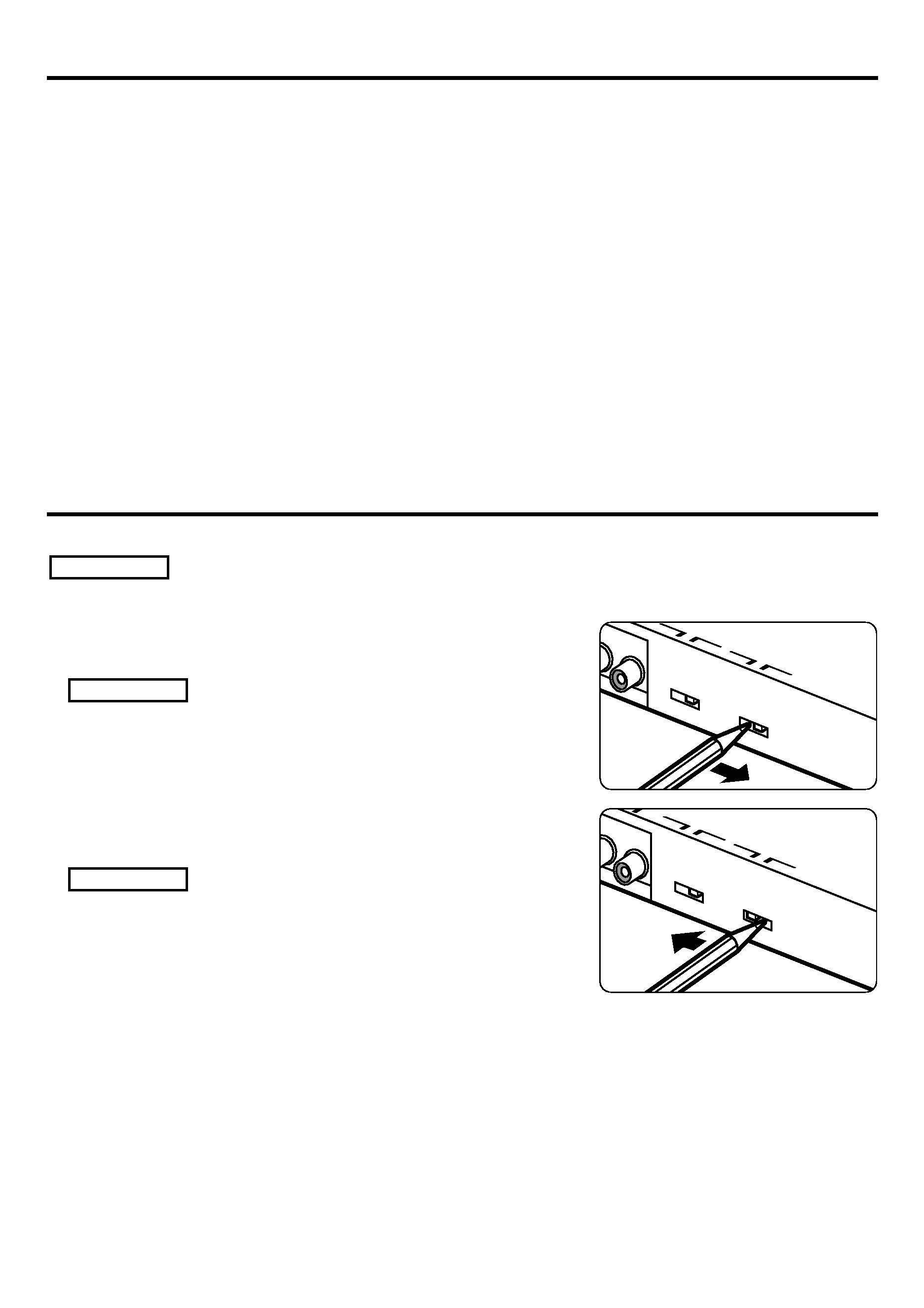
Setting the PROTOCOL switch
You will need to set the PROTOCOL switch according to the centre unit you wish to connect.
Turn the centre unit power off before operating the PROTOCOL switch.
2CAUTION
AUX
S
OFF
ON
PROTOCOL
SWITCH
O
N
AUX
SWI
OFF
ON
PROTOCOL
SWITCH
O
N
If the unit you are connecting belongs to Group A or
Group B
Set the PROTOCOL switch to the "O" position.
If you move the PROTOCOL switch to the "N" position, the
switching unit will become inoperable. (If the disc changer you
have connected has an O-N switch, set it to the "O" position
also.)
If the unit you are connecting belongs to Group C or
Group D
Set the PROTOCOL switch to the "N" position.
· If you move the PROTOCOL switch to the "O" position,
then even if you have connected a disc changer supporting
CD text, the CD text and the disc name (DNPS) will fail to be
displayed on the centre unit. (If the connected disc
changer has an O-N switch, set it to the "N" position also.)
· If the disc changer you are connecting does not have an O-
N switch, you will not be able to use the disc name setting
(DNPS) function.
2CAUTION
2CAUTION

Reviews

There are no reviews of this manual yet.