KCA-RC50MR
Marine Remote Control
Installation Instructions
Mounting The Remote Control:
1. Select a mounting location that is flat and 1/2" thick or less.
2. Using the supplied rubber gasket as a template, drill the mounting holes and a hole for the wiring
at the desired locations.
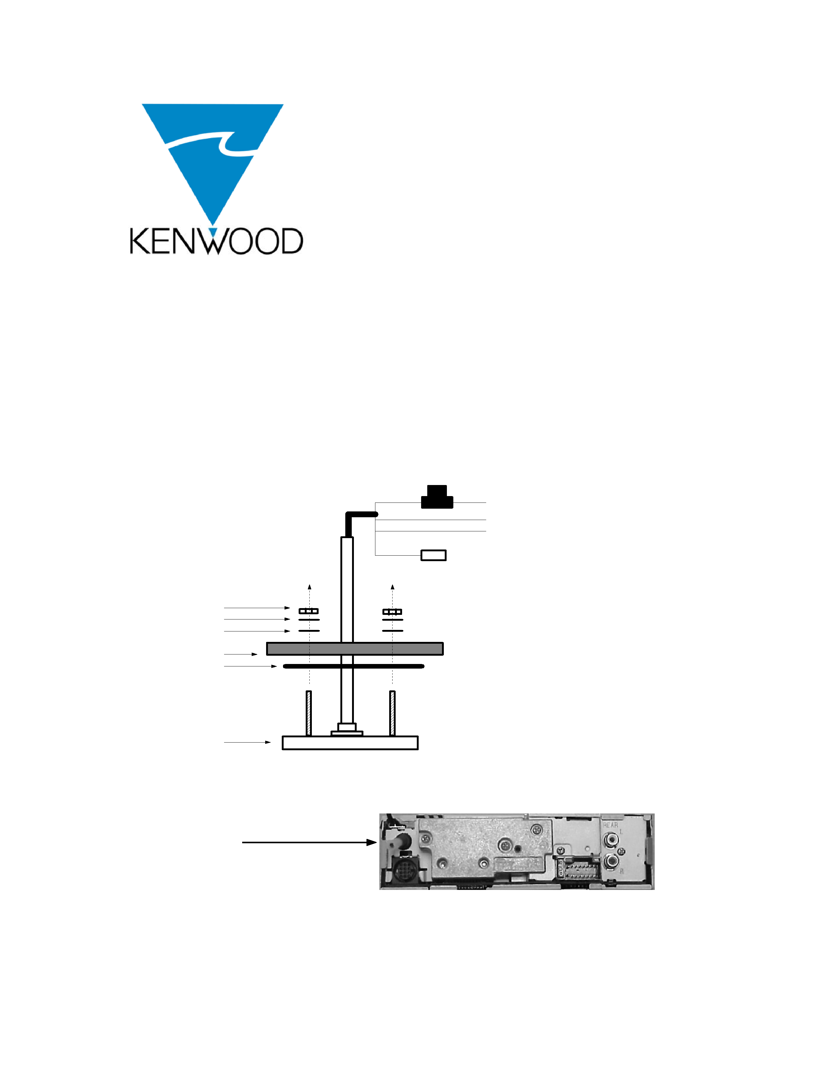
3. Mount the remote control according to the diagram in FIG. 1 using supplied hardware.
4. Connect the electrical wiring for power, illumination, and ground as shown in FIG. 1.
Connect supplied data line to remote, route to the radio and connect to the connector on the
rear of the radio as shown in FIG. 2.
Data Line Connection
Point:
Note, The rear view of radio and location
of connection point will vary dependent
on radio model.
FIG. 2
2 AMP FUSE
RED
+ 12V switched/ignition
YELLOW Illumination (connect to instrument lighting)
BLACK:
ground
BLUE
Data line (connect to radio)
FIG. 1
NUT
LOCK WASHER
WASHER
MOUNT ING SURFACE
GASKET
REMOT E


