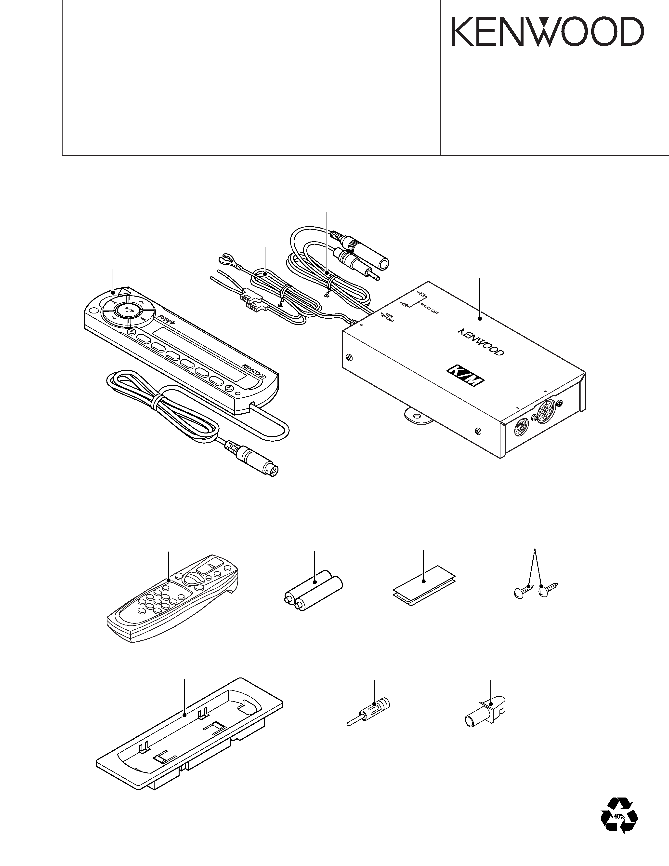
KENWOOD KCA-R71FM Service Manual

Cover page of KENWOOD KCA-R71FM Service Manual

Service Manual for KENWOOD KCA-R71FM, downloadable as a PDF file.

We also have owner's manual to this model.

Manual details

  • Immediate download after payment.
  • Delivered as a PDF file.
  • The manual has 18 pages
  • File size: 0.63 MB
  • Available language versions: English
  • Different language versions may vary sligthly in file size and page count.

We guarantee that...

  • our manuals are complete,
  • the manual includes circuit diagrams,
  • our manuals are checked with antivirus,
  • We'll issue refund if the manual is damaged, incomplete or unreadable (our refund policy)

Sample pages

Thumbnail of page 1Thumbnail of page 2Thumbnail of page 3Thumbnail of page 4
Thumbnail of page 5Thumbnail of page 6Thumbnail of page 7Thumbnail of page 8
Thumbnail of page 9
background image
© 2004-2 PRINTED IN JAPAN
B53-0149-00 (N) 2438
FM MODULATOR
KCA-R71FM
SERVICE MANUAL
Size AAA battery
(Not supplied)
(E type only)
(E type only)
SR
C
PW
R
OF
F
SR
CH
/
ME
NU
1
2
3
4
5
6
SC
AN
RD
M
RE
P
M.R
DM
DIS
P
PO
W
ER
INPUT
DISP
.
INPUT
INPUT
CO
NT
RO
LLE
R
FM
S
TE
RE
O
MO
DU
LAT
OR
FR
EQ
UE
NC
Y:(
MH
z)
87.7
/8
7.9
/8
8.1
/8
8.3
/8
8.5
88.7
/8
8.9
/8
9.1
/8
9.3
/8
9.5
89.7
/8
9.9
KENW
OOD
CORPORA
TION
MADE
IN
KOREA
Metallic cabinet
K type: (A01-2850-08)
E type: (A01-2852-08)
Remote controller assy
K type: (A70-2051-05) (RC-535)
E type: (A70-2052-05) (RC-525)
Velcro
(W01-1633-08)
Unit holder
(J19-7009-08)
Serew
(N99-1755-08) x2
Antenna adaptor
(T90-0512-05)
Antenna adaptor
(T90-0521-05)
Cord with plug
(E30-6376-08)
DC cord assy
(E30-6377-08)
Panel assy
K type : (A64-3412-08)
E type : (A64-3414-08)
background image
KCA-R7
1FM
2
BLOCK
DIA
GRAM
background image
KCA-R71FM
3
COMPONENTS DESCRIPTION
CONTROL UNIT
Ref. No.
Application / Function
Operation / Condition / Compatibility
IC701
LCD Driver with Key-matrix
IC702
Remote Control Light Sensor
Q701
LED ON/OFF SW
Q702
Key-matrix Permission SW
Q703
Remote Control ON/OFF SW
FM MODULATOR UNIT
Ref. No.
Application / Function
Operation / Condition / Compatibility
IC101,102
GND Isolation AMP
IC103
Low Pass Filter
IC301
FM Stereo Modulator
IC302
1/2 Vcc Driver, ALC Detection Amp
IC501
System
µcom
IC601
6V AVR
Q102
L/R Mixer SW
D.cont off : L, D.cont on : H
Q103,203
ALC Control SW
Q151,251
Pre-out Mute
Q152,153
Pre-out Mute Control
Q301
Composite Buffer
Q351
Temperature compensation
Q303,304
Level Control SW
LEVEL 1/2 : L, LEVEL 3/4 : H, LEVEL 2/4 : L, LEVEL 1/3 : H
Q305
Audio Mute
Power on : L, Power off : H
Q401,402
PLL Low Pass Filter
Q411
RF Amp
Q501
Changer Reset SW
Q502
Reset SW
Q601,602
Display Unit Power SW
Q603
Backup 5V AVR
Q604,605
Power SW
Q606
8V AVR
Q607
Relay Driver
Q608
ACC Detection
Q609
Hold Detection
background image
KCA-R71FM
4
MICROCOMPUTER'S TERMINAL DESCRIPTION
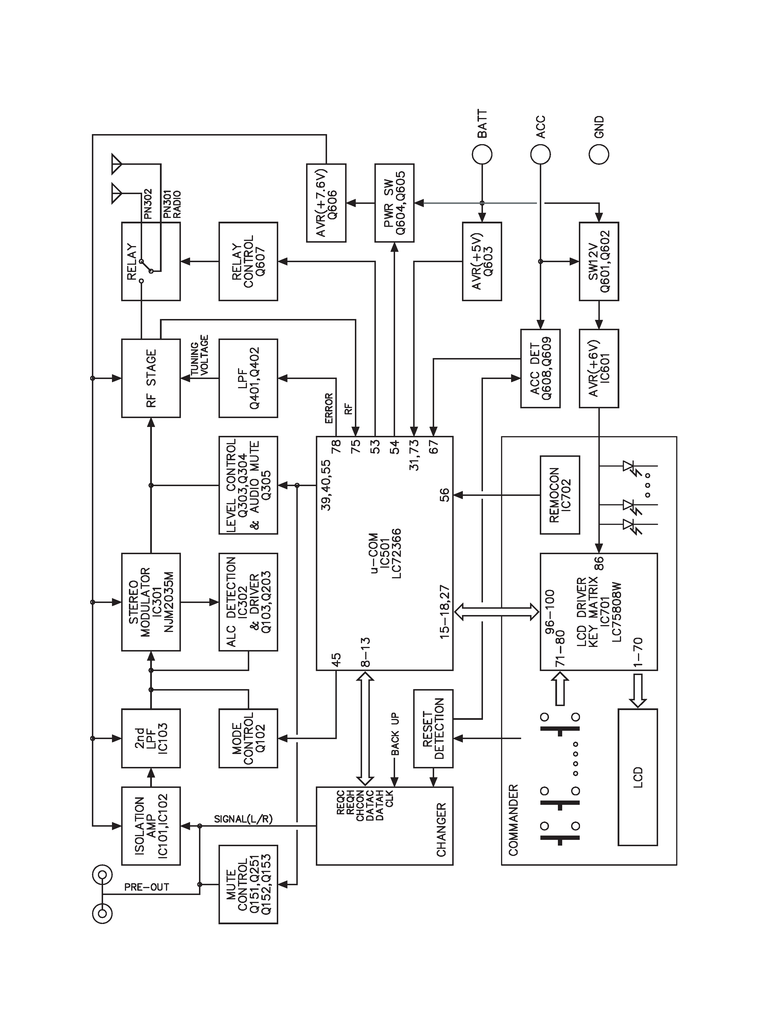
SYSTEM MICROCOMPUTER : LC72366-9B63 (FM MODULATOR UNIT : IC501)
Pin No.
Pin Name
I/O
Terminal name
Description
Operation in HOLD
1
XIN
I
X IN
X_tal
-
2
TEST2
-
GND
Ground connection terminal
-
3~5
PG3~1
O
NC
Not used (pull down to GND lines.)
L
6
PG0
I
GND
Connected to GND lines.
-
7
PF3
O
NC
Not used (open)
L
8
PF2
I
REQC
CD-Changer REQC (Active "Low")
-
9
PF1
O
REQH
CD-Changer REQH (Active "Low")
H
10
PF0
O
CHCON
CD-Changer ON
L
11
SI2
I
CH_DATA_C
CD-Changer DATA in
-
12
SO2
O
CH_DATA_H
CD-Changer DATA out
L
13
SCK2
O
CH_CLK
CD-Changer DATA SCK (Active "Low")
H
14
PE0
O
NC
Not used (open)
L
15
PD3
O
LCD DATA out
LCD Driver DATA out
L
16
PD2
O
LCD CLK
LCD Driver CLK out
L
17
PD1
O
LCD RESET
LCD Driver RESET out
L
18
PD0
O
LCD CE
LCD Driver CE out
L
19~26
PC3~PB0
O
NC
Not used (open)
L
27
PA3
I
LCD DATA in
LCD Driver DATA in
-
28~30
PA2~0
I
NC
Not used (pull down to GND lines.)
-
31
VDD
-
Vdd
5V
-
32
PQ0
O
NC
Not used (open)
L
33~44
PP3~PN0
O
GAIN12~1
Modulation output switching
L
45
PM3
O
SEP-ATT
When it has GAIN5 output, "Hi" output
L
46~52
PM2~PL0
O
NC
Not used (open)
L
53
PK3
O
RELAY
Antenna relay control output terminal
L
54
PK2
O
P-on
P_ON
L
55
PK1
O
MUTE
Mute output terminal for the Tuner frequency change
L
56
INT0
I
REMOCON
Remote controller signal input
57~60
PJ3~0
O
NC
Not used (open)
L
61~66
PI1~PH0
I
NC
Not used (pull down to GND lines.)
-
67
HOLD
I
HOLD
ACC detection (Operation in HOLD "Low")
L
68
SNS
I
Vdd
Vdd
-
69
LCTR
I
NC
Not used (pull down to GND lines.)
-
70
HCTR
I
NC
Not used (pull down to GND lines.)
-
71
EO3
O
NC
Not used (open)
Hi-Z
72
SUBPD
O
NC
Not used (open)
Hi-Z
73
VDD
-
Vdd
Vdd
-
74
AMIN
I
NC
Not used (pull down to GND lines.)
-
75
FMIN
I
VCO in
VCO input
-
background image
KCA-R71FM
5
Pin No.
Pin Name
I/O
Terminal name
Description
Operation in HOLD
76
VSS
-
Vss
Vss
-
77
EO2
O
NC
Not used (open)
Hi-Z
78
EO1
O
Error out
Phase Detector Error output
Hi-Z
79
TEST1
-
NC
Not used (pull down to GND lines.)
-
80
XOUT
O
X-out
X-tal
MICROCOMPUTER'S TERMINAL DESCRIPTION
ADJUSTMENT
Instrument :
SSG, OSC (5MHz), AC VOLTMETER, PWR SUPPLY, H/UNIT, CD-CH
RECEIVER
ALIGNMENT
No.
ITEM
INPUT SETTINGS
OUTPUT SETTINGS
(MODULATOR)
POINTS
ALIGN FOR
FIG.
FREQ
L/R Balance
CD-CH cignal off
Connect a
1
Adj.
(Tr No.29 or Pause)
Oscilloscope
88.3MHz
VR301
Min Level
(a)
to Q301 Base.
1. Ref.FM 1kHz 80dB
µV
Connect a
Difference between
2
Moduration
Stereo, CD-CH Tr No.1
AC voltmeter
88.3MHz
VR302
FM and a CD-CH
level Adj.
2. D.Cont Off MOD Lv:2
to Receiver PreOut
level is adjusted to
(-0.5
±1.0dB).
* After Adj. The glue is applied to VR301, VR302.
(Scope Setting Condition for L/R BAL. Adj.)
1. VOLTAGE RANGE : 5mV
2. TIME/DIV : 50
µs
Adjusted to be
min level point
(Before Adj.)
(After Adj.)
Fig. (a)

Reviews

There are no reviews of this manual yet.