KENWOOD KAF-S500 Service Manual

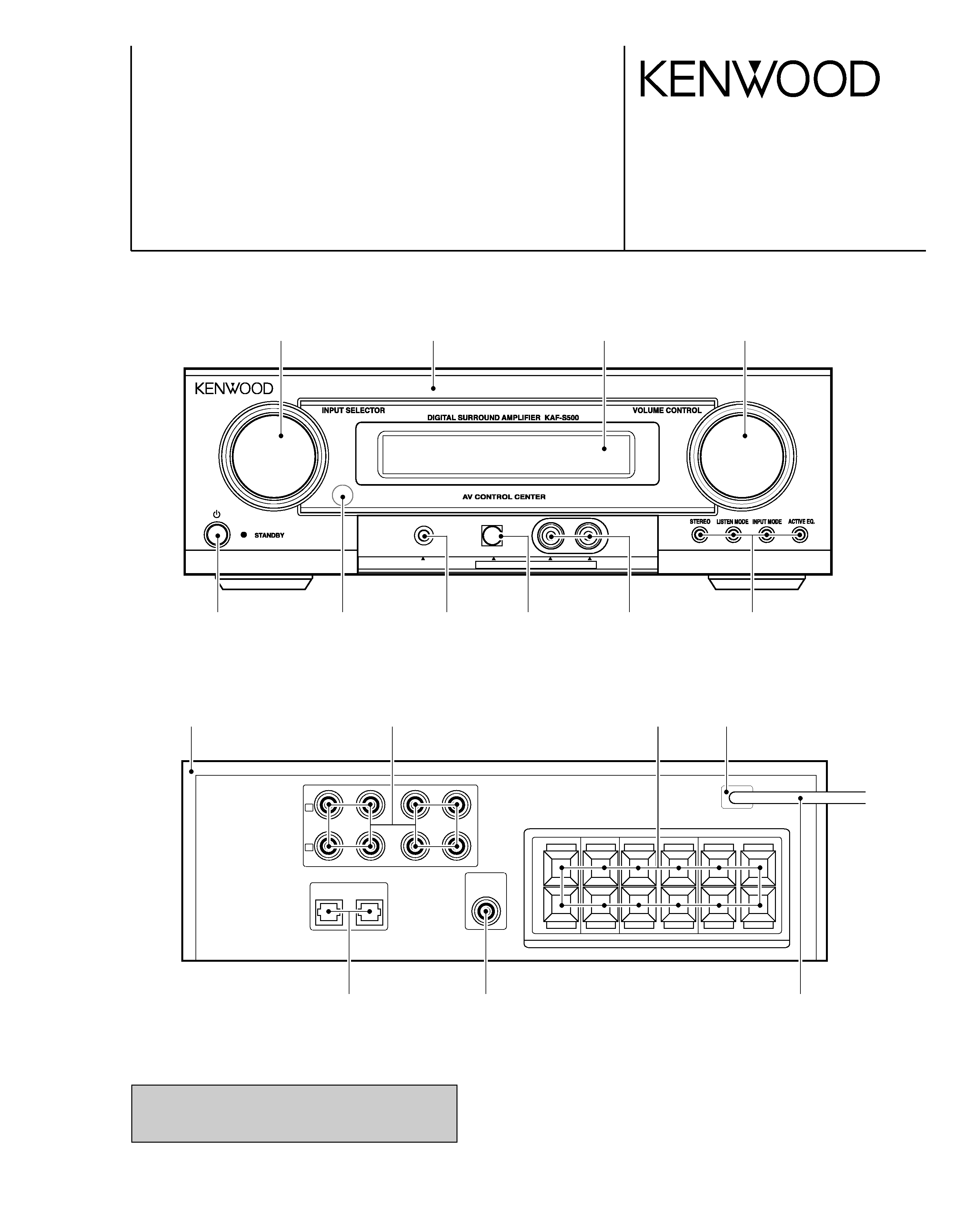
Cover page of KENWOOD KAF-S500 Service Manual

Service Manual for KENWOOD KAF-S500, downloadable as a PDF file.

We also have owner's manual to this model.

Manual details

  • Immediate download after payment.
  • Delivered as a PDF file.
  • The manual has 19 pages
  • File size: 2.22 MB
  • Available language versions: English
  • Different language versions may vary sligthly in file size and page count.

We guarantee that...

  • our manuals are complete,
  • the manual includes circuit diagrams,
  • our manuals are checked with antivirus,
  • We'll issue refund if the manual is damaged, incomplete or unreadable (our refund policy)

Sample pages

Thumbnail of page 1Thumbnail of page 2Thumbnail of page 3Thumbnail of page 4
Thumbnail of page 5Thumbnail of page 6Thumbnail of page 7Thumbnail of page 8
Thumbnail of page 9
background image
PHONES
AUX
OPTICAL
L -AUDIO -R
DIGITAL SURROUND AMPLIFIRE
KAF-S500
SERVICE MANUAL
© 2003-9 B51-5877-00 (K/K) PDF
Caution : No connection of ground line if disassemble
the unit. Please connect the ground line on
rear panel, PCBs, Chassis and some others.
Panel
(A60-2372-08)
Knob
(K29-8340-08)
Knob
(K29-8338-08)
Knob
(K29-8339-08)
Knob
(K29-8340-08)
Window
(B10-3995-08)
Filter
(B11-1594-08)
DVD/CD
OPT1
OPT 2
SUB
WOOFER
IN-VIDEO 2 IN
VIDEO 1
SPEAKERS
IN
OUT
L
R
Stopper
(J42-0358-08)
Casing ass'y
(A10-3611-08)
Ter,Rca
(E63-1333-08)x2
Ter,Board
(E70-0187-08)
Ter,Rca
(E63-1334-08)
Cord ass'y
(E30-7308-08)
Module
(W02-4525-08)x2
Jack
(E11-0973-08)
Module
(W02-4525-08)
Ter,Rca
(E63-1332-08)
(HTB-S500DV)
background image
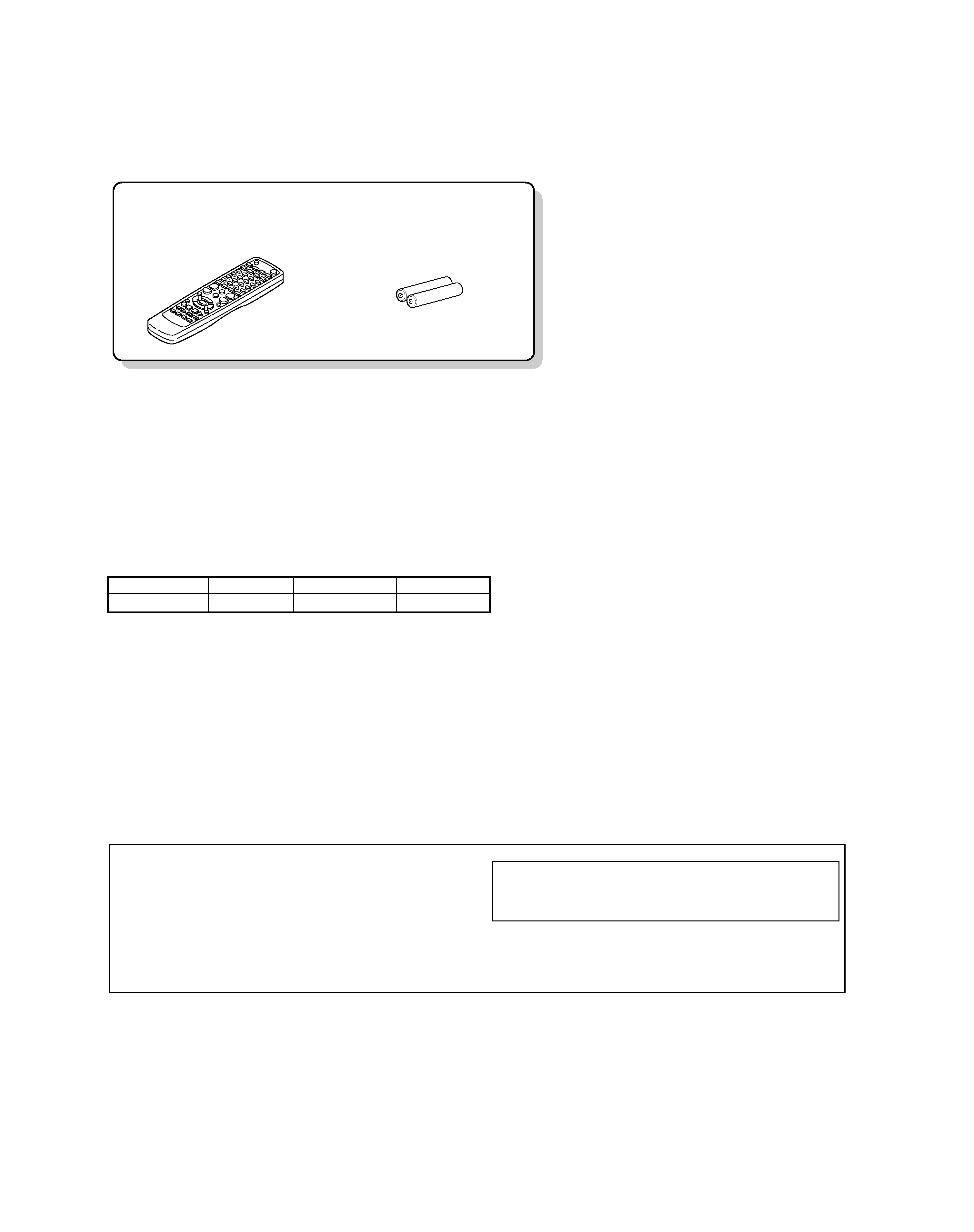
Batteries (R03/AAA) (2)
Remote control unit (1)
(A70-1644-08)
KAF-S500
2
ACCESSORIES / CAUTIONS
Accessories
Resetting the Microcomputer
The microcomputer may malfunction (unit cannot be
operated, or shows an erroneous display) if the power
cord is unplugged while the power is ON, or due to
some other external factor. If this happens, execute the
following procedure to reset the microcomputer and
return the unit to its normal operating condition.
Unplug the power cord after turn the POWER key
OFF. Then, while holding down the POWER key, plug
the power cord.
· Please note that resetting the microcomputer will clear
the contents of the memory and returns the unit to the
state it was in when it left the factory.
Cautions
SYSTEM
AMPLIFIER
DVD PLAYER
SPEAKERS
HTB-S500DV
KAF-S500
DVF-S500
KSW-S500
background image
3
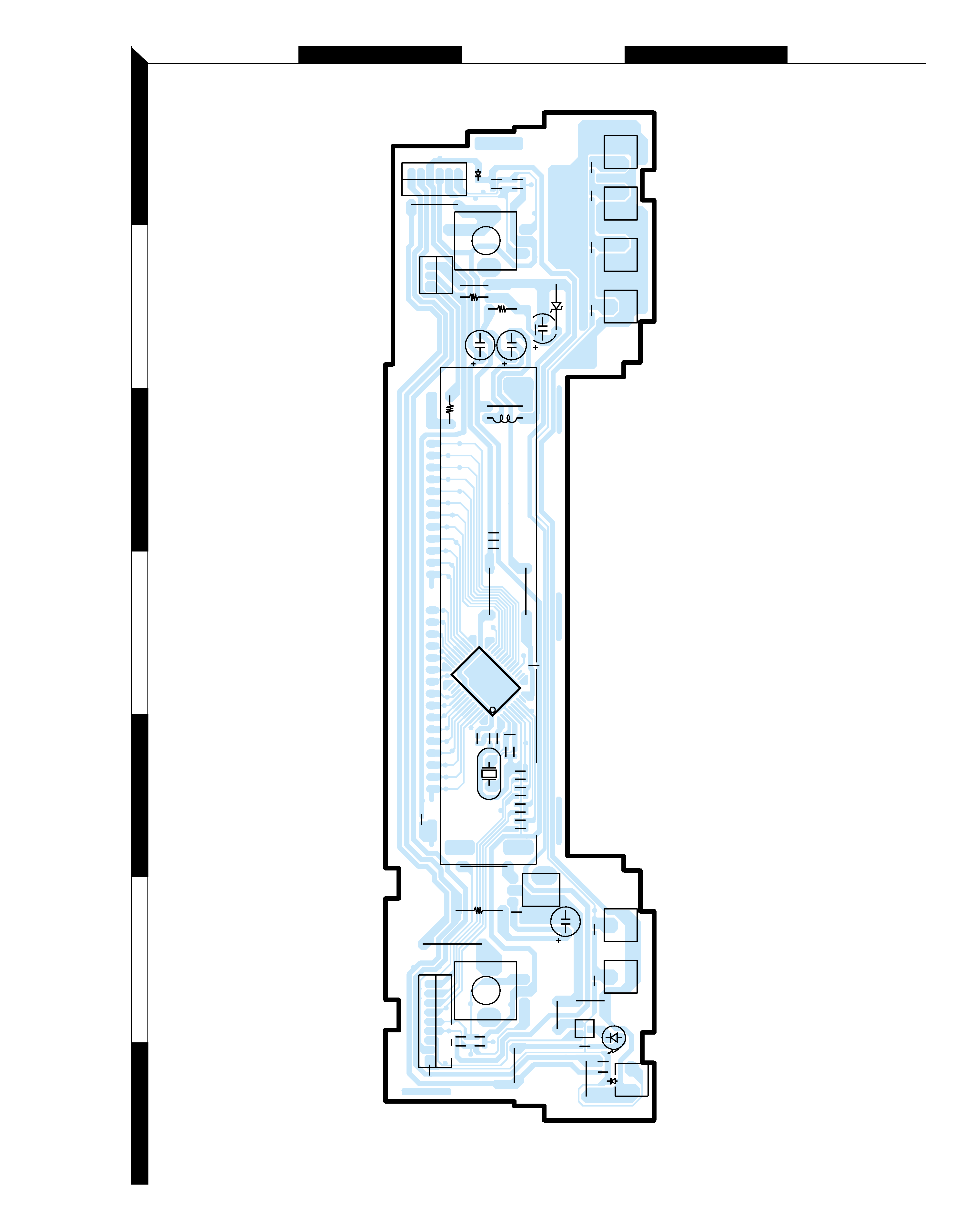
Refer to the schematic diagram for the value of resistors and capacitors.
PC BOARD
AC
E
BD
2
1
3
5
7
4
6
SW101
D106
LED101
Q102
SW103
SW102
ZD101
SW104
SW105
SW107
SW106
D103
CN101
CN103
REM101
CN102
IC101
R124
B
E
R103
R102
R105
R104
C107
C104
C108
C127
C130
C128
C129
R101
C102
C103
C106
R113
C131
R
111
1
14
15
24 25
38
39
48
C132
C133
R106
J107
C1
10
C1
16
L101
R109
R112
C105
J109
R127
61
R128
C120
C119
VR102
R120
R1
18
R1
19
LISTEN M
ACTIVE
EQ.
INPUT M
STEREO
C126
R1
16
R1
15
R1
17
DOWN
TUNE
UP
R114
POWER
J108
LUG103
31
1
5
34
38
1
9
LUG
C118
C117
R126
R125
C124
J101
J103
J102
J104
J113
VR101
C109
R107
J110
X101
J106
J105
C1
15
FRONT
background image
4
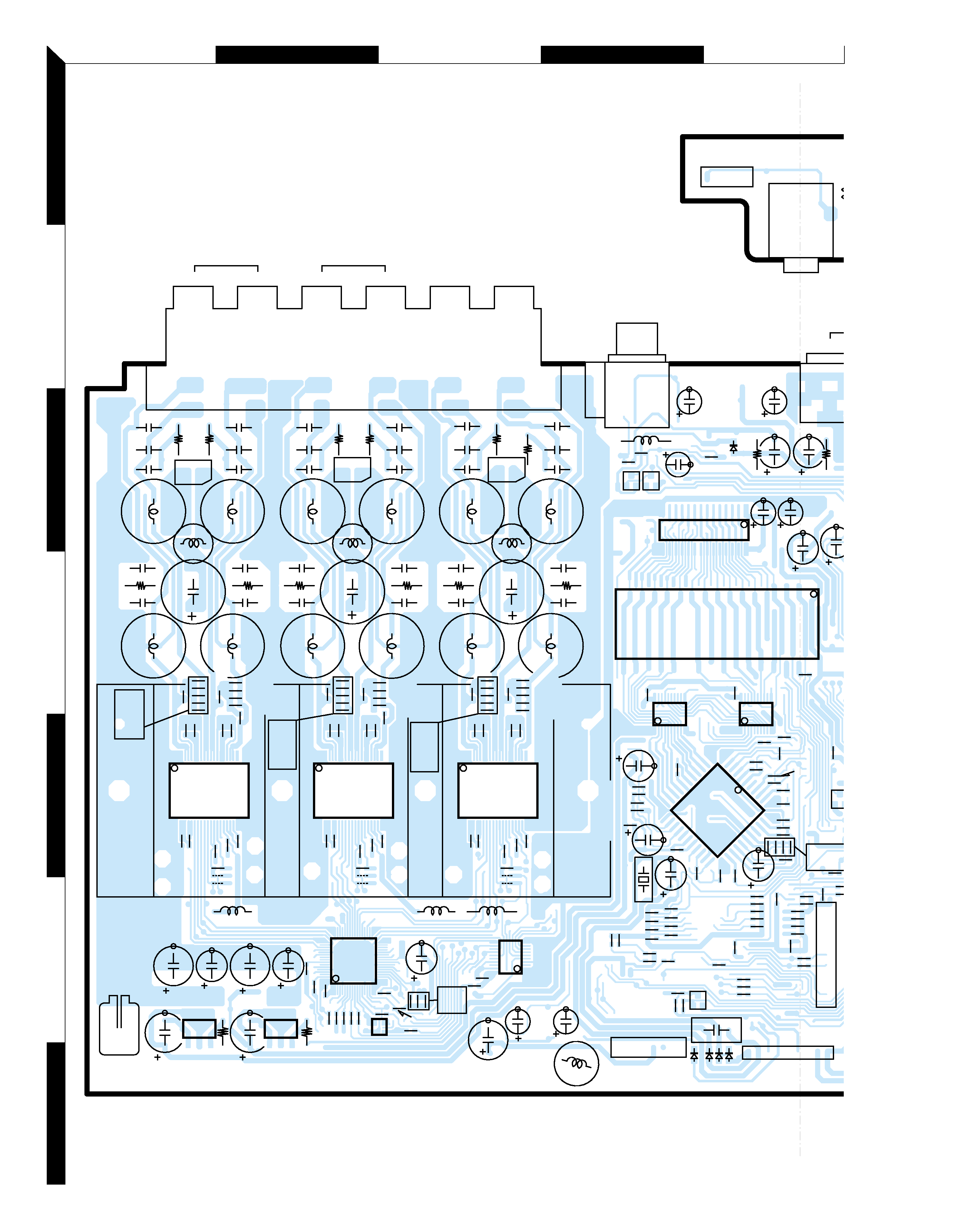
Refer to the schematic diagram for the value of resistors and capacitors.
PC BOARD
F
GI
HJ
2
1
3
5
7
4
6
E
17
16
R347
R685
R687
R681
OPEN
R697
C665
C668
X200
R254
R256
R238
R240
L300
R807
R831
C804
R826
R835
R841
C824
C844
R845
C353
OPEN
GND
GND801
C215
R281
C861
C860
C862
C355
J802
J801
R818
36
R801
R806
C800
C803
C801
1
R800
C207
R316
R31
1
C216
R282
R331
R333
R332
R330
L201
C302
C867
C865
C866
C868
C863
C307
C356
C354
R303
R304
L815
R334
C301
C303
C360
R317
OPEN J804
J803
R819
C823
R834
19
C864
36
R813
C802 18
R825
R827
1
R833
R829
C869
19
C822
C821
C820
R839
18
R838
R837
C872
OPEN
C432
C304
R289
C212
L816
L817
J806
J805
R820
C213
OPEN
R207
R208
C874
C870
36
C871
C873
R844
C843
1
R843
R840
C842
C840
C841
19
18
R849
R848
R847
C667
L812
C811
R803
C807
L801
R812
C805
C876
C813
C809
L803
C815
L800
MAIN1
R805
R802
C828
R810
C825
L802
R828
L805
R809
C831
C827
C808
R804
C812
L806
R832
C877
R836
L813 C832
L807
C810
C806
12
12
12
C829
C833
C814
C835
MAIN1
L804
C830
C826
R81
1
R808
C834
R842
C845
C847
L809
C878
R815
C851
C848
R846
L808
L814
C852
R816
R814
MAIN1
C853
L811
C849
C855
R817
C850
L810
C846
B
R350
C854
C655
C656
R235
to SMPS
B
R272
29
C653
R672
R227
C202
R285
R244
R241
R242
R243
R239
R228
R232
OPEN
R205
R206 R283
BE
R275
R257
R253
R674
C200
R255
R676
R677
R258
R261
R212
OPEN
OPEN
R221
R218
R219
OPTION
RDS
R211
R671
R262
R260
R264
R263
R259
C654
OPEN
R251
OPEN
R252
C660
C651
C650
18
17
28
7
6
R680
C652
C659
39
40
R679
1
15
R684
R670
R669
R678
R683
R686
R688
R682
R691
C220
E
C601
R659
32
C658
1
C606
C318
BE
R357
C331
C657
R315
C334
R314
C333
C328
to
to MAIN
L102
1
14
15
28
20
11
110
20
11
110
1
10
20
11
116
48
33
32
17
64
49
OG I
I
G
O
3
1
16
9
9
1
1
4
5
CP203
Q312
RCA803
IC203
IC800
IC202
IC303
IC300
IC801
IC204
IC802
CP804
JACK801
CP805
CP806
CN801
D200
D204
D201
D202
Q202
CP200
IC600
IC602
IC601
OPT40
VIDEO
O
D
IC603
D303
Q311
IC604
SUB
WOOFER
SUB
WOOFER
CENTER
R
L
R
FRONT
L
PHONES
JACK103
CN104
REAR
SUB (SIDE-A)
MAIN
(SIDE-B)
background image
5
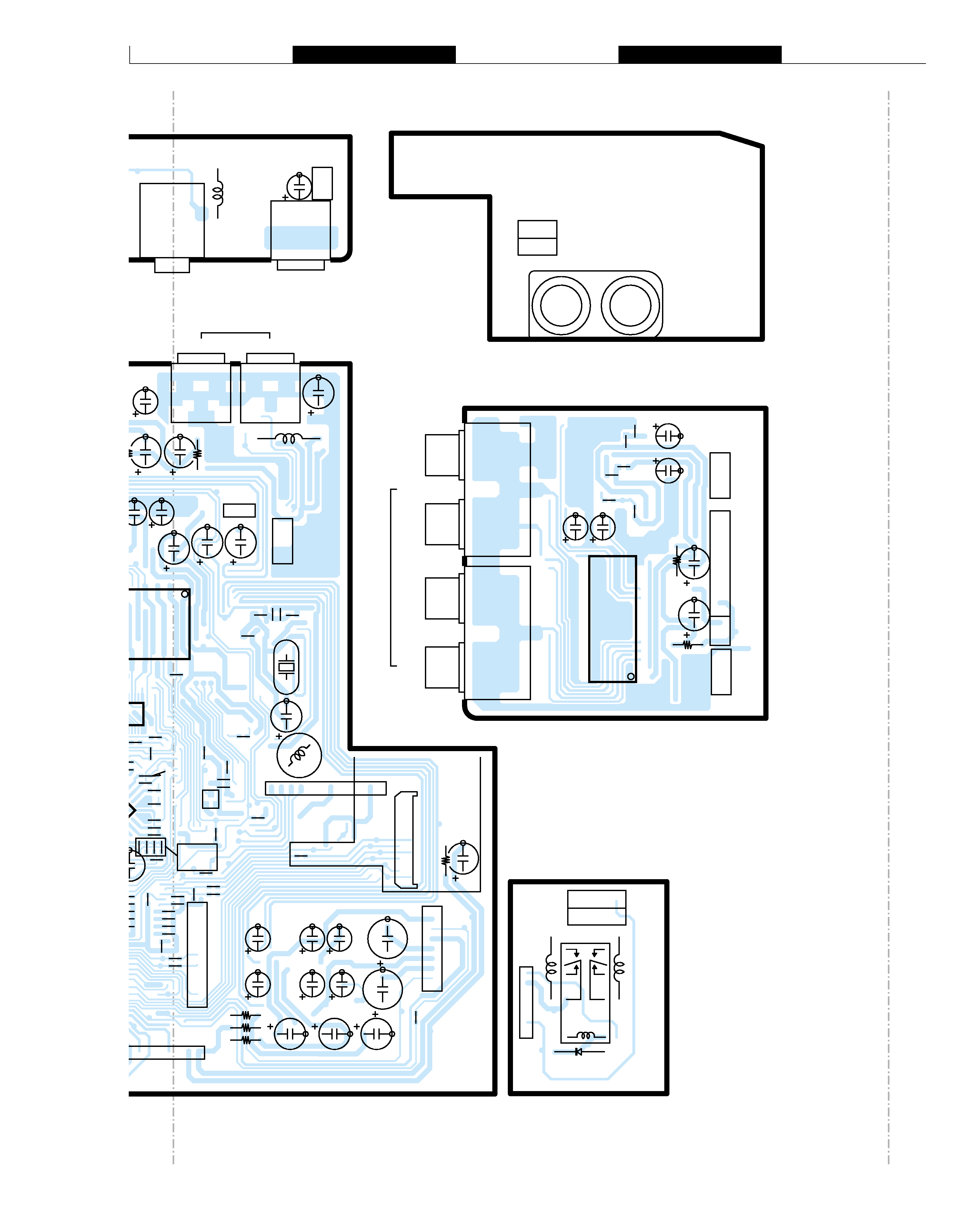
Refer to the schematic diagram for the value of resistors and capacitors.
PC BOARD
KM
O
LN
R277
from TUNER
R313
to SMPS
R348
C346
B
R270
C222
R272
C653
R672
R258
R261
R212
OPEN
OPEN
R221
R218
R219
PTION
DS
R211
R671
R262
R260
R264
R263
R259
4
OPEN
R251
OPEN
R252
C660 R680
C652
C659
39
40
R679
12
1
3
1
3
1
1
1
1
12
1
1
3
3
3
3
R684
R670
R669
R678
R683
R686
82
R691
C220
OPEN
R271
OPTION
C315
C314
R349
C351
C308
C309
OPTION
TUNER
OPEN
R290
OPEN
R279
C317
OPEN
C321
C350
C316
C320
OPEN
from INPUT B'D
R623
C221
E
R288
R500
L200
C609
TUNER
from
AUX
from
SUB
B'D
H/P
MUTE
C208
R237
RL
Y301
L301
L302
OPEN
OPEN
28
R436
1
C601
R659
32
8
1
C606
C657
C334
R314
C333
C328
R625
R614
C602
C607
X601
R628
C605
to INPUT B'D
from
OPT
B'D
L400
C435
L102
LUG101
C122
to
INPUT
to MAIN
to
MAIN
to
MAIN
15
C412
R428
C411
R429
14
C414
C413
R437
C428
C429
BD401
BD400
C420
C419
LUG102
11
10
9
1
1
7
7
1
1
51
J
A
CK401
CN801
Q200
CP200
IC601
CW400
CP201
HP
D301
CP801
CP802
CN803
CP403
J
A
CK402
VIDEO2
OUT
OPT401
VIDEO2
OPTICAL
DIGITAL IN
VIDEO1
A
UDIO
DV
D
OPT400
CW401
CP402
DVD/CD
OPT101
PHONES
OPTICAL
AUX
JACK103
CN106
CP400
CP401
IC401
CN105
LR
AUDIO
AUX
JACK101
IN
E-A)
AUX (SIDE-B)
INPUT (SIDE-B)
H/P MUTE (SIDE-B)

Reviews

There are no reviews of this manual yet.