2 English
Safety precautions
To prevent injury or fire, take the following
precautions:
· When extending the ignition, battery, or
ground wires, make sure to use automotive-
grade wires or other wires with a 8mm2
(AWG8) or more to prevent wire deterioration
and damage to the wire coating.
· To prevent a short circuit, never put or leave
any metallic objects (such as coins or metal
tools) inside the unit.
· If the unit starts to emit smoke or strange
smells, turn off the power immediately and
consult your Kenwood dealer.
· Do not touch the unit during use because the
surface of the unit becomes hot and may
cause burns if touched.
To prevent damage to the machine, take the
following precautions:
· Be sure the unit is connected to a 12V DC
power supply with a negative ground
connection.
· Do not open the top or bottom covers of the
unit.
· Do not install the unit in a spot exposed to
direct sunlight or excessive heat or humidity.
Also avoid places with too much dust or the
possibility of water splashing.
· When replacing a fuse, only use a new one
with the prescribed rating. Using a fuse with
the wrong rating may cause your unit to
malfunction.
· To prevent a short circuit when replacing a
fuse, first disconnect the wiring harness.
· If you experience problems during
installation, consult your Kenwood dealer.
· If the unit does not seem to be working right,
consult your Kenwood dealer.
FCC WARNING
This equipment may generate or use radio
frequency energy. Changes or modifications
to this equipment may cause harmful
interference unless the modifications are
expressly approved in the instruction manual.
The user could lose the authority to operate
this equipment if an unauthorized change or
modification is made.
This Class B digital apparatus complies with
Canadian ICES-003.
Cleaning the unit
If the front panel gets dirty, turn off the power
and wipe the panel with a dry silicon cloth or
soft cloth.
Do not wipe the panel with a hard cloth or a
cloth dampened by volatile solvents such as
paint thinner and alcohol. They can scratch the
surface of the panel and/or cause the indicator
letters to peel off.
To prevent batter rise
When the unit is used in the ACC ON position
without turning the engine ON, it depletes the
battery. Use it after starting the engine.
Protection function
There is a Protection function installed in the
unit to protect the unit and speakers from
various problems. When Protection operates,
the indicator informs you of the condition.
(Refer to page 6)
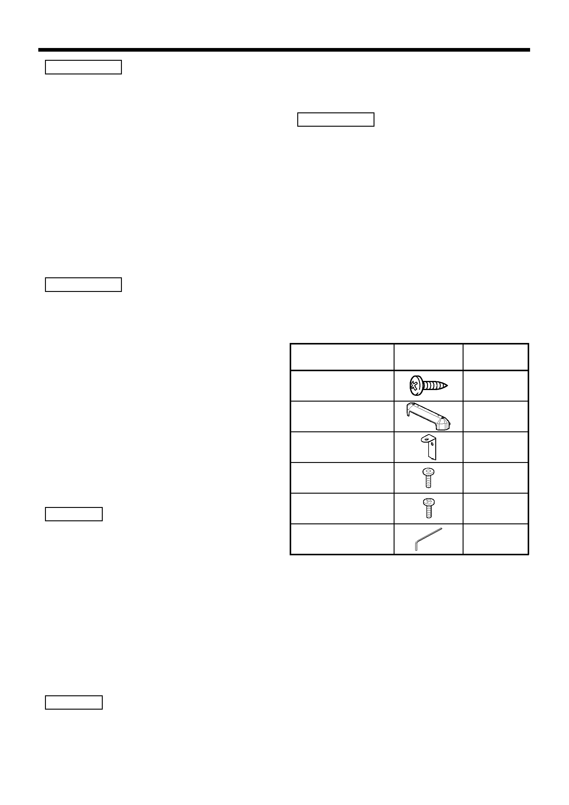
Accessories
2CAUTION
NOTE
NOTE
2CAUTION
2WARNING
Part name
Number of
Items
External
View
Self-tapping screws
(ø5
× 18 mm)
4
Terminal cover
2
Mounting Hardware
4
Hexagon socket head
cap screw (M3
× 8 mm)
4
Self-tapping screws
(ø3
× 8 mm)
4
Hexagon Wrench
1