KENWOOD KAC-X4D Owner's Manual

Cover page of KENWOOD KAC-X4D Owner's Manual

Owner's Manual for KENWOOD KAC-X4D, downloadable as a PDF file.

Manual details

  • Immediate download after payment.
  • Delivered as a PDF file.
  • The manual has 36 pages
  • File size: 2.23 MB
  • Available language versions: Japanese, English
  • Different language versions may vary sligthly in file size and page count.

We guarantee that...

  • our manuals are complete,
  • our manuals are checked with antivirus,
  • We'll issue refund if the manual is damaged, incomplete or unreadable (our refund policy)

Sample pages

Thumbnail of page 1Thumbnail of page 2Thumbnail of page 3Thumbnail of page 4
Thumbnail of page 5Thumbnail of page 6Thumbnail of page 7Thumbnail of page 8
Thumbnail of page 9
background image
XR-4S
KAC-X4D
FOUR CHANNEL DIGITAL POWER AMPLIFIER
3 page 2-13
INSTRUCTION MANUAL
AMPLIFICATEUR 4 CANAUX DIGITAL
3 page 14-25
MODE D'EMPLOI
AMPLIFICADOR DE POTENCIA DIGITAL DE CUATRO CANALES
3 página 26-36
MANUAL DE INSTRUCCIONES
© B64-4324-00/00 (KV/EV)
Take the time to read through this instruction manual.
Familiarity with installation and operation procedures will help you obtain the best
performance from your new power amplifier.
For your records
Record the serial number, found on the back of the unit, in the spaces designated on the
warranty card, and in the space provided below. Refer to the model and serial numbers
whenever you call upon your Kenwood dealer for information or service on the product.
Model XR-4S/KAC-X4D Serial number
US Residence Only
Register Online
Register your Kenwood product at
www.Kenwoodusa.com
XR-4S_KE_1English.indd 1
08.12.18 5:35:47 PM
background image
English
Safety precautions
WARNING
To prevent injury or fire, take the following
precautions:
· Mounting and wiring this product requires skills and
experience. For safety's sake, leave the mounting and
wiring work to professionals.
· When extending the ignition, battery, or ground
wires, make sure to use automotive-grade wires or
other wires with the range of 14 mm² (AWG 6) to
21 mm² (AWG 4) to prevent wire deterioration and
damage to the wire coating.
· To prevent a short circuit, never put or leave any
metallic objects (such as coins or metal tools) inside
the unit.
· If the unit starts to emit smoke or strange smells,
turn off the power immediately and consult your
Kenwood dealer.
· Do not touch the unit during use because the
surface of the unit becomes hot and may cause
burns if touched.
CAUTION
To prevent damage to the machine, take the
following precautions:
· Be sure the unit is connected to a 12V DC power
supply with a negative ground connection.
· Do not open the top or bottom covers of the unit.
· Do not install the unit in a spot exposed to direct
sunlight or excessive heat or humidity. Also avoid
places with too much dust or the possibility of water
splashing.
· When replacing a fuse, only use a new one with the
prescribed rating. Using a fuse with the wrong rating
may cause your unit to malfunction.
· To prevent a short circuit when replacing a fuse, first
disconnect the wiring harness.
NOTE
· If you experience problems during installation,
consult your Kenwood dealer.
· If the unit does not seem to be working right,
consult your Kenwood dealer.
FCC WARNING
This equipment may generate or use radio
frequency energy. Changes or modifications to this
equipment may cause harmful interference unless
the modifications are expressly approved in the
instruction manual. The user could lose the authority
to operate this equipment if an unauthorized change
or modification is made.
FCC NOTE
This equipment has been tested and found to
comply with the limits for a Class B digital device,
pursuant to Part 15 of the FCC Rules. These limits are
designed to provide reasonable protection against
harmful interference in a residential installation. This
equipment may cause harmful interference to radio
communications, if it is not installed and used in
accordance with the instructions. However, there
is no guarantee that interference will not occur in a
particular installation. If this equipment does cause
harmful interference to radio or television reception,
which can be determined by turning the equipment
off and on, the user is encouraged to try to correct
the interference by one or more of the following
measures:
· Reorient or relocate the receiving antenna.
· Increase the separation between the equipment
and receiver.
· Connect the equipment into an outlet on a
circuit different from that to which the receiver is
connected.
· Consult the dealer or an experienced radio/TV
technician for help.
NOTE
This Class B digital apparatus complies with Canadian
ICES-003.
Declaration of Conformity with
regard to the EMC Directive
004/108/EC
Manufacturer:
Kenwood Corporation
2967-3 Ishikawa-machi, Hachioji-shi, Tokyo,
192-8525 Japan
EU Representative's:
Kenwood Electronics Europe BV
Amsterdamseweg 37, 1422 AC UITHOORN,
The Netherlands
XR-4S_KE_1English.indd 2
08.12.18 5:35:48 PM
background image
English
Information on Disposal of Old Electrical
and Electronic Equipment (applicable for
EU countries that have adopted separate
waste collection systems)
Products with the symbol (crossed-out
wheeled bin) cannot be disposed as
household waste.
Old electrical and electronic equipment
should be recycled at a facility capable
of handling these items and their waste
byproducts. Contact your local authority
for details in locating a recycle facility
nearest to you. Proper recycling and waste
disposal will help conserve resources whilst
preventing detrimental effects on our
health and the environment.
This Product is not installed by the manufacturer of a
vehicle on the production line, nor by the professional
importer of a vehicle into an EU Member State.
Cleaning the unit
If the front panel gets dirty, turn off the power and
wipe the panel with a dry silicon cloth or soft cloth.
CAUTION
Do not wipe the panel with a hard cloth or a cloth
dampened by volatile solvents such as paint thinner
and alcohol. They can scratch the surface of the panel
and/or cause the indicator letters to peel off.
To prevent battery rise
When the unit is used in the ACC ON position without
turning the engine ON, it depletes the battery. Use it
after starting the engine.
Protection function
The protection function is activated in the following
situations:
This unit is equipped with a protection function for
protecting this unit and your speakers from various
accidents or problems that can occur.
When the protection function is triggered, the
PROTECTION indicator lights and the amplifier stops
operating.
· When a speaker wire may be short-circuited.
· When a speaker output contacts ground.
· When the unit malfunctions and a DC signal is sent
to the speaker output.
7 Wiring
· Take the battery wire for this unit directly from the
battery. If it's connected to the vehicle's wiring
harness, it can cause blown fuses etc.
· If a buzzing noise is heard from the speakers when
the engine is running, connect a line noise filter
(optional) to each of the battery wire.
· Do not allow the wire to directly contact the edge of
the iron plate by using Grommets.
· Connect the ground wire to a metal part of the car
chassis that acts as an electrical ground passing
electricity to the battery`s negative
· terminal.
Do not turn the power on if the ground wire is not
connected.
· Be sure to install a protective fuse in the power
cord near the battery. The protective fuse should
be the same capacity as the unit's fuse capacity or
somewhat larger.
· For the power cord and ground, use a vehicle type
(fireproof ) power wring cord with a current capacity
greater than the unit's fuse capacity. (Use a power
wiring cord with the range of 14 mm² (AWG 6) to 21
mm² (AWG 4).
· When more than one power amplifier are going
to be used, use a power supply wiring wire and
protective fuse of greater current-handling capacity
than the total maximum current drawn by each
amplifier.
7 Speaker Selection
· The rated input power of the speakers that are
going to be connected should be greater than the
maximum output power (in Watts) of the amplifier.
Use of speakers having input power ratings that
are less than the output power of the amplifier will
cause smoke to be emitted as well as damage.
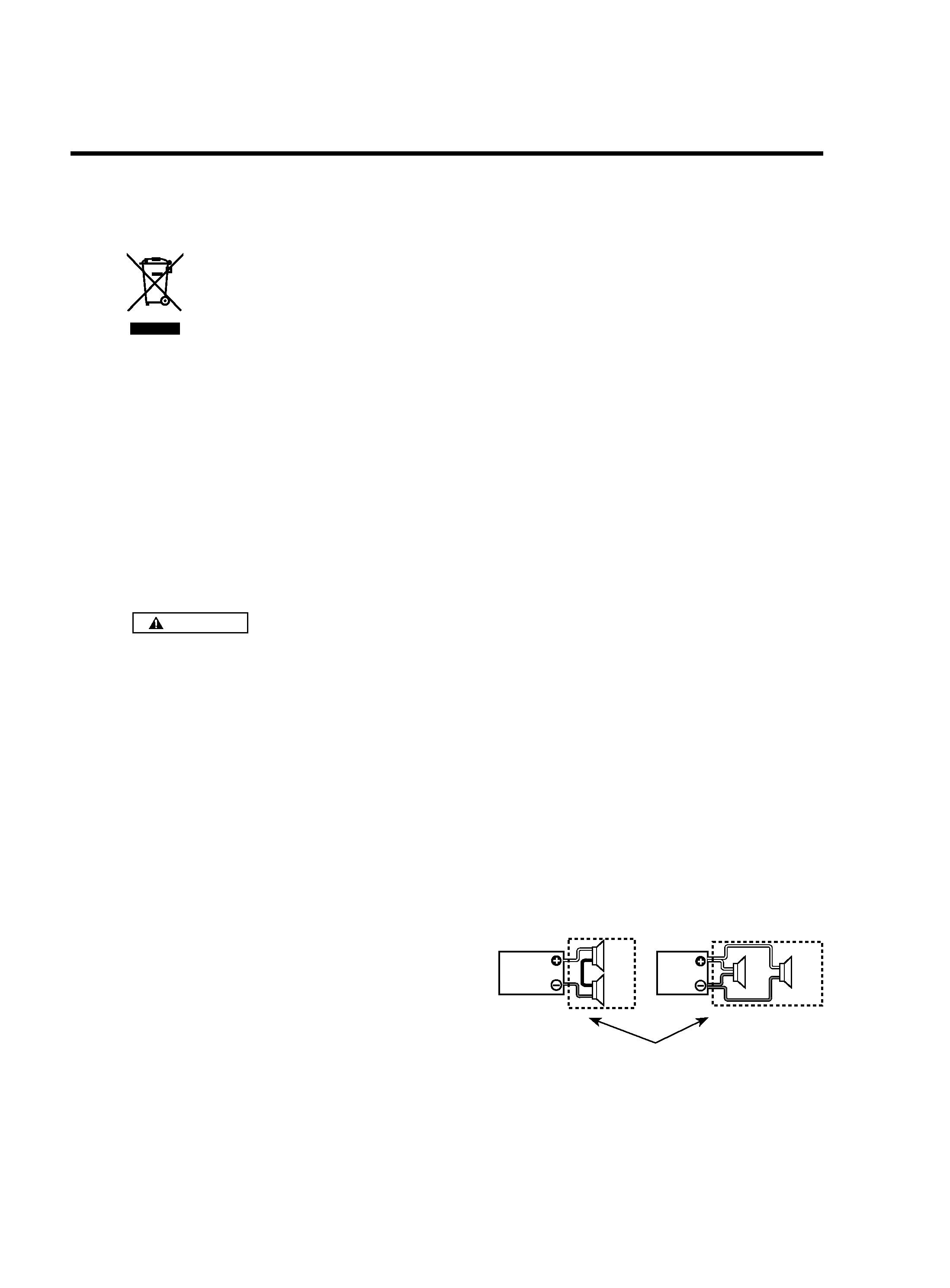
· The impedance of the speakers that are going
to be connected should be 2 or greater (for
stereo connections), or 4 or greater (for bridged
connections). When more than one set of speakers
are going to be used, calculate the combined
impedance of the speakers and then connect
suitable speakers to the amplifier.
4
4
8
2
2
4
4
4
4
4
4
4
4
4
8
4
4
4
4
4
4
4
4
4
Combined impedance
XR-4S_KE_1English.indd 3
08.12.18 5:35:48 PM
background image
4 English
Installation
7 Accessories
Part name
External
View
Number
of Items
Self-tapping screws
(ø5 × 18 mm (3/16" × 11/16"))
4
Hexagon Wrench (Large)
1
Hexagon Wrench (Small)
1
Terminal cover (Power
terminal)
1
7 Installation procedure
Since there are large variety of settings and
connections possible according to applications, read
the instruction manual well to select the proper
setting and connection.
1. Remove the ignition key and disconnect the
negative
· terminal of the battery to prevent short
circuits.
2. Set the unit according to the intended usage.
3. Connect the input and output wires of the units.
4. Connect the speaker wires.
5. Connect the power wire, power control wire and
grounding wire following this order.
6. Install the installation fittings in the unit.
7. Attach the unit.
8. Connect the negative
· terminal of the battery.
235 mm (9-1/4")
217 mm (8-9/16")
ø 6 (1/4")
192
mm
(7-9/16")
162
mm
(6-3/8")
CAUTION
· Do not install in the below locations;
(Unstable location, In a location that interferes
with driving, In a location that gets wet, In a dusty
location, In a place that gets hot, In a place that
gets direct sunlight, In a location that gets hit by
hot air)
· Do not install the unit under the carpet.
Otherwise heat build-up occurs and the unit may
be damaged.
· Install this unit in a location which allows heat to
easily dissipate.
Once installed, do not place any object on top of
the unit.
· The surface temperature of the amplifier will
become hot during use. Install the amplifier in a
place where people, resins, and other substances
that are sensitive to heat will not come into
contact with it.
· This unit has cooling fan to decrease the internal
temperature. Do not mount the unit in a place
where the cooling fan and ducts of the unit are
blocked. Blocking these openings will inhibit the
cooling of the internal temperature and result in
malfunction.
· When making a hole under a seat, inside the
trunk, or somewhere else in the vehicle, check
that there is nothing hazardous on the opposite
side such as a gasoline tank, brake pipe, or wiring
harness, and be careful not to cause scratches or
other damage.
· Do not install near the dashboard, rear tray, or air
bag safety parts.
· The installation to the vehicle should securely
fasten the unit to a place in which it will not
obstruct driving. If the unit comes off due to a
shock and hits a person or safety part, it may
cause injury or an accident.
· After installing the unit, check to make sure that
electrical equipment such as the brake lamps,
turn signal lamps and windshield wipers operate
normally.
Installation board, etc.
(thickness : 15 mm (9/16") or more)
Self-tapping screw
(ø5 × 18 mm (3/16" × 11/16"))
XR-4S_KE_1English.indd 4
08.12.18 5:35:49 PM
background image
English
XR-4S_KE_1English.indd 5
08.12.18 5:35:49 PM

Reviews

There are no reviews of this manual yet.