2 English
Safety precautions
2WARNING
To prevent injury or fire, take the following precautions:
· When extending the ignition, battery, or ground wires, make sure to use
automotive-grade wires or other wires with a 8 mm2 (AWG 8) or more to
prevent wire deterioration and damage to the wire coating.
· To prevent a short circuit, never put or leave any metallic objects (such as
coins or metal tools) inside the unit.
· If the unit starts to emit smoke or strange smells, turn off the power
immediately and consult your Kenwood dealer.
· Do not touch the unit during use because the surface of the unit becomes
hot and may cause burns if touched.
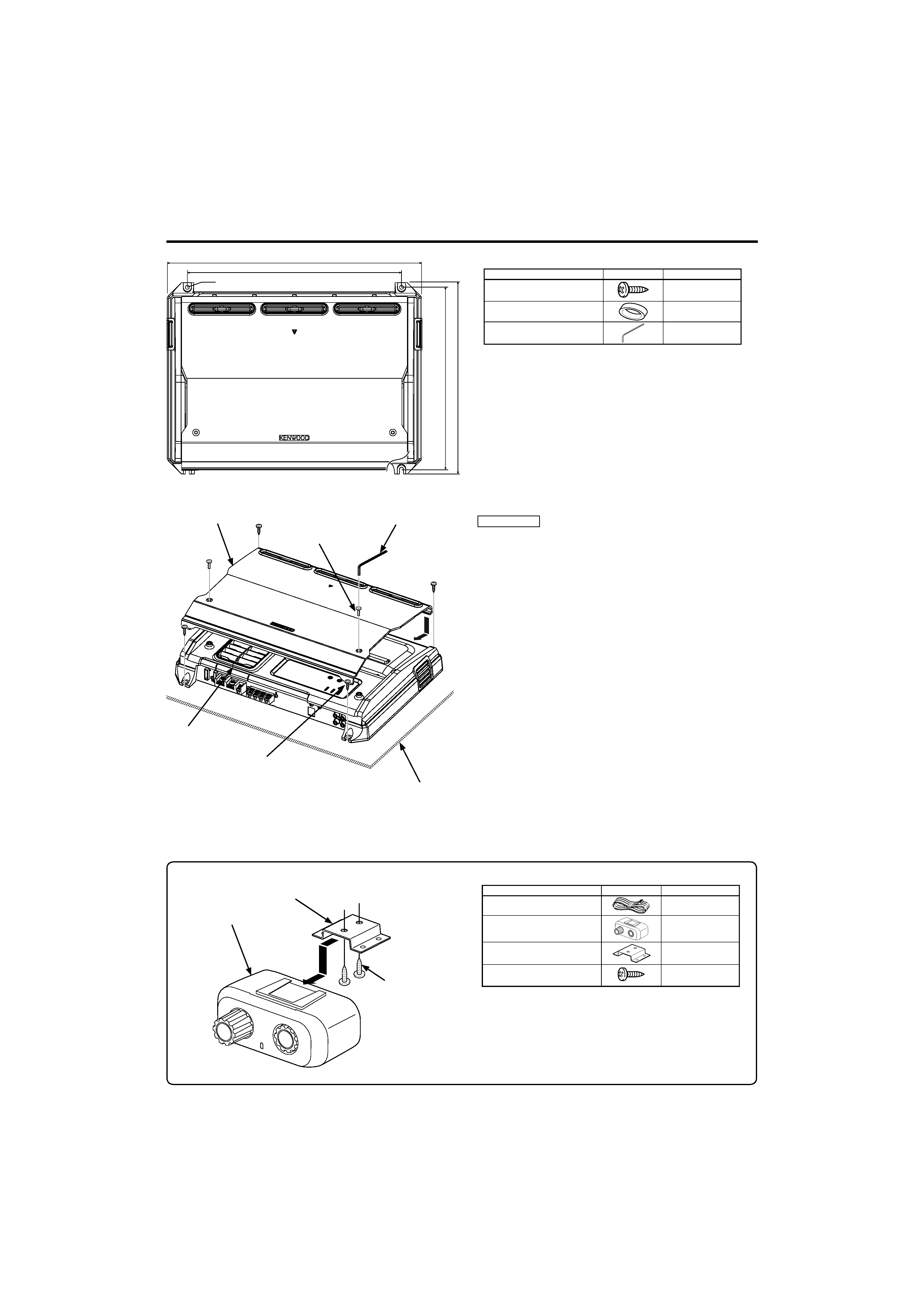
· Mounting and wiring this product requires skills and experience. For safety's
sake, leave the mounting and wiring work to professionals.
2CAUTION
To prevent damage to the machine, take the following
precautions:
· Be sure the unit is connected to a 12V DC power supply with a negative
ground connection.
· Do not open the top or bottom covers of the unit.
· Do not install the unit in a spot exposed to direct sunlight or excessive heat
or humidity. Also avoid places with too much dust or the possibility of water
splashing.
· When replacing a fuse, only use a new one with the prescribed rating. Using a
fuse with the wrong rating may cause your unit to malfunction.
· To prevent a short circuit when replacing a fuse, first disconnect the wiring
harness.
NOTE
· If you experience problems during installation, consult your Kenwood dealer.
· If the unit does not seem to be working right, consult your Kenwood dealer.
FCC WARNING
This equipment may generate or use radio frequency energy. Changes or
modifications to this equipment may cause harmful interference unless the
modifications are expressly approved in the instruction manual. The user could
lose the authority to operate this equipment if an unauthorized change or
modification is made.
FCC NOTE
This equipment has been tested and found to comply with the limits for a
Class B digital device, pursuant to Part 15 of the FCC Rules. These limits are
designed to provide reasonable protection against harmful interference in
a residential installation. This equipment may cause harmful interference to
radio communications, if it is not installed and used in accordance with the
instructions. However, there is no guarantee that interference will not occur
in a particular installation. If this equipment does cause harmful interference
to radio or television reception, which can be determined by turning the
equipment off and on, the user is encouraged to try to correct the interference
by one or more of the following measures:
· Reorient or relocate the receiving antenna.
· Increase the separation between the equipment and receiver.
· Connect the equipment into an outlet on a circuit different from that to which
the receiver is connected.
· Consult the dealer or an experienced radio/TV technician for help.
Cleaning the unit
If the front panel gets dirty, turn off the power and wipe the panel with a dry
silicon cloth or soft cloth.
2CAUTION
Do not wipe the panel with a hard cloth or a cloth dampened by volatile
solvents such as paint thinner and alcohol. They can scratch the surface of the
panel and/or cause the indicator letters to peel off.
To prevent battery rise
When the unit is used in the ACC ON position without turning the engine ON, it
depletes the battery. Use it after starting the engine.
Protection function
The protection function is activated in the following situations:
This unit is equipped with a protection function for protecting this unit and your
speakers from various accidents or problems that can occur.
When the protection function is triggered, the Power indicator goes OFF and
the amplifier stops operating.
· When a speaker wire may be short-circuited.
· When a speaker output contacts ground.
· When the unit malfunctions and a DC signal is sent to the speaker output.
· When the internal temperature is high and unit won't operate.
· When a ground wire of the center unit (cassette receiver, CD receiver, etc.)
or this unit is not connected to a metal part serving as an electrical ground
passing electricity to the battery's negative
- terminal.
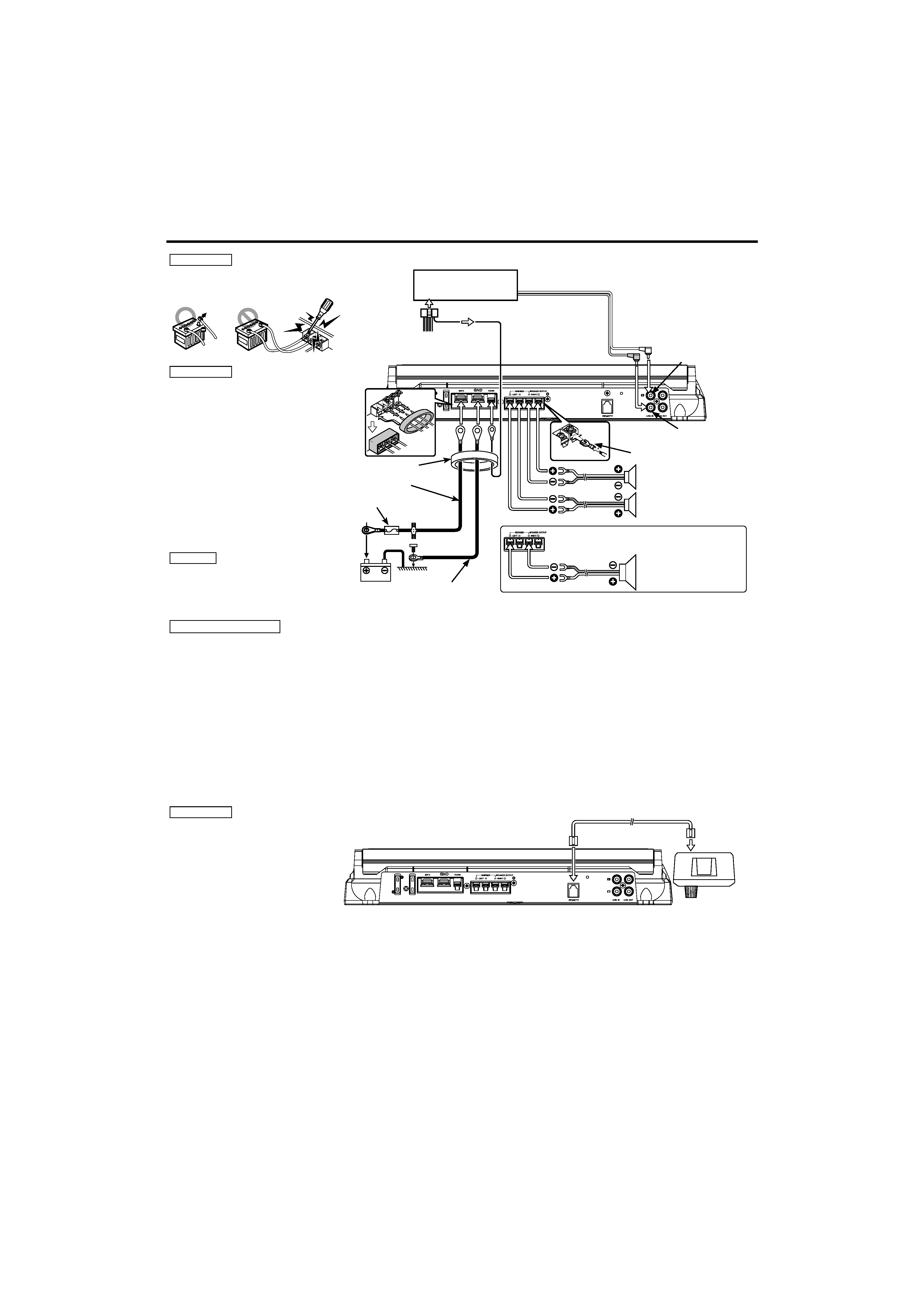
Wiring
· Take the battery wire for this unit directly from the battery. If it's connected to
the vehicle's wiring harness, it can cause blown fuses etc.
· If a buzzing noise is heard from the speakers when the engine is running,
connect a line noise filter (optional) to each of the battery wire.
· Do not allow the wire to directly contact the edge of the iron plate by using
Grommets.
· Connect the ground wire to a metal part of the car chassis that acts as an
electrical ground passing electricity to the battery`s negative
- terminal. Do
not turn the power on if the ground wire is not connected.
· Be sure to install a protective fuse in the power cord near the battery. The
protective fuse should be the same capacity as the unit's fuse capacity or
somewhat larger.
· For the power cord and ground, use a vehicle type (fireproof ) power wring
cord with a current capacity greater than the unit's fuse capacity. (Use a power
wiring cord with a diameter of 8 mm2 (AWG 8) or greater.)
· When more than one power amplifier are going to be used, use a power
supply wiring wire and protective fuse of greater current-handling capacity
than the total maximum current drawn by each amplifier.
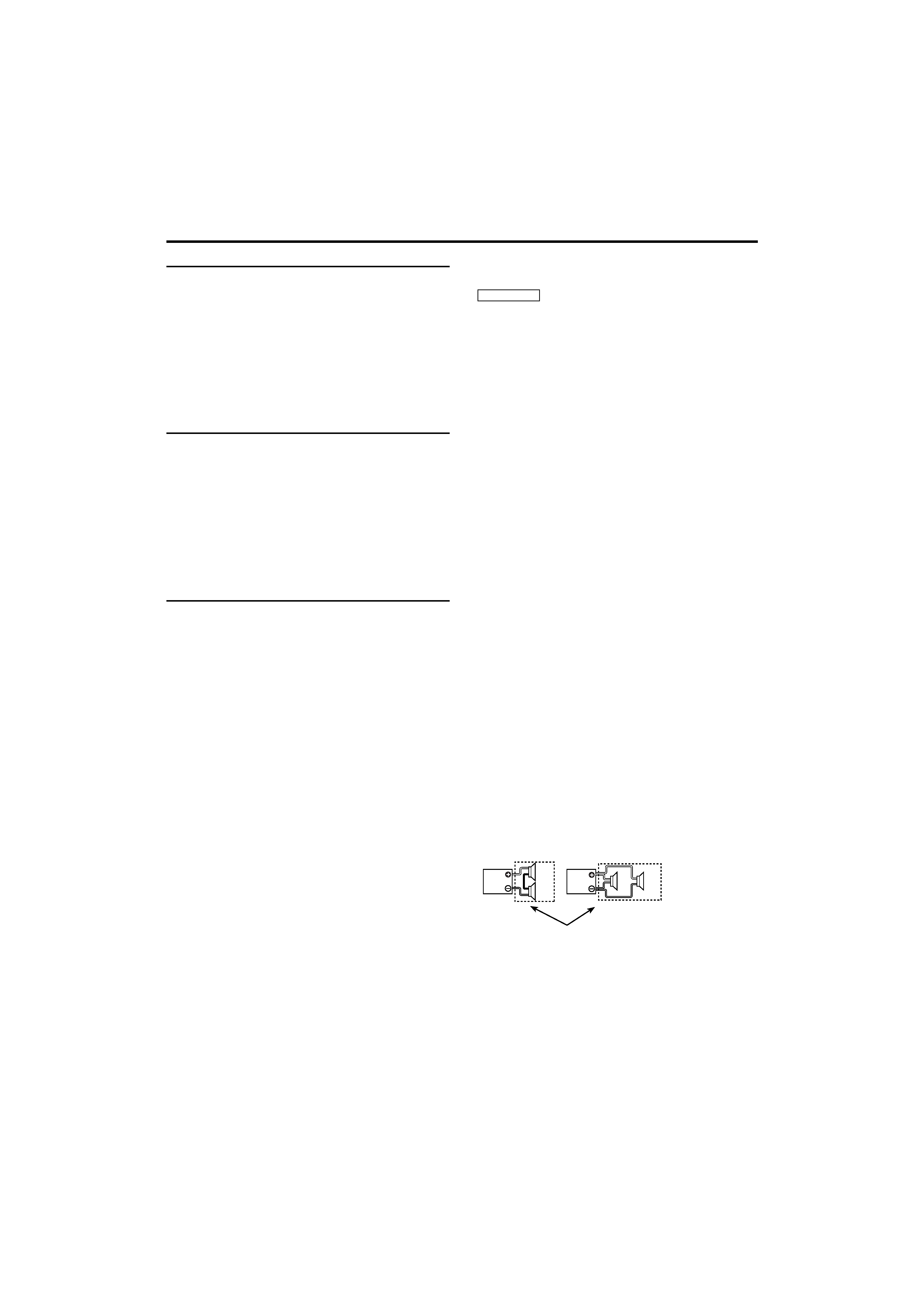
Speaker Selection
· The rated input power of the speakers that are going to be connected should
be greater than the maximum output power (in Watts) of the amplifier. Use of
speakers having input power ratings that are less than the output power of
the amplifier will cause smoke to be emitted as well as damage.
· The impedance of the speakers that are going to be connected should be 2
or greater (for stereo connections), or 4 or greater (for bridged connections).
When more than one set of speakers are going to be used, calculate the
combined impedance of the speakers and then connect suitable speakers to
the amplifier.
8
2
4
4
4
4
Combined impedance