KENWOOD KAC816 Owner's Manual

Cover page of KENWOOD KAC816 Owner's Manual

Owner's Manual for KENWOOD KAC816, downloadable as a PDF file.

Manual details

  • Immediate download after payment.
  • Delivered as a PDF file.
  • The manual has 9 pages
  • File size: 0.15 MB
  • Available language versions: English
  • Different language versions may vary sligthly in file size and page count.

We guarantee that...

  • our manuals are complete,
  • our manuals are checked with antivirus,
  • We'll issue refund if the manual is damaged, incomplete or unreadable (our refund policy)

Sample pages

Thumbnail of page 1Thumbnail of page 2Thumbnail of page 3Thumbnail of page 4
Thumbnail of page 5Thumbnail of page 6Thumbnail of page 7Thumbnail of page 8
Thumbnail of page 9
background image
KAC-816
MONO POWER AMPLIFIER
INSTRUCTION MANUAL
© PRINTED IN MEXICO B64-1170-00 (EM)
background image
KAC-816
MONO POWER AMPLIFIER
INSTRUCTION MANUAL
© PRINTED IN MEXICO B64-1170-00 (EM)
background image
2
Safety precautions
Take the following precautions to
prevent fire and avoid personal
injury :
· When extending the battery cable, or
ground cable, use 5mm2 (AWG10) or
larger automotive grade cable to avoid
cable deterioration or damage to the
covering.
· Check that no metal objects (coins, tools,
etc.) are left inside the unit to avoid short
circuits.
· If you smell or see smoke, turn the
power off immediately and consult your
Kenwood dealer.
· Do not touch the unit during use because
the surface of the unit becomes hot and
may cause burns if touched.
Take the following precautions to
keep the unit in proper working
order.
· Be sure the unit is connected to a 12V
DC power supply with a negative ground
connection.
· Do not open the top or bottom cover.
· Do not install the unit in places it is
exposed to direct sunlight, high heat or
humidity, water may splash over it, or
dust exists.
If you have difficulty in installing this unit
in your vehicle, contact your Kenwood
dealer.
Cleaning the unit
If the surface is dirty, wipe it clean with a
silicon cloth or soft dry cloth with the
power off.
Do not use hard cloths or paint thinner,
alcohol, or other volatile solvents. These
may damage external surfaces or remove
indicator characters.
2CAUTION
NOTE
2CAUTION
2WARNING
Accessories
Part name
Number
of Items
External
View
Battery cable
(Yellow) (6 m)
1
Ground cable (Black)
(1 m)
1
Self-tapping screws
(ø4
× 16 mm)
4
Terminal cover
(Power terminal)
1
Part name
Number
of Items
External
View
Round terminal
(Large)
1
Round terminal
(Medium)
2
Round terminal
(Small)
1
Grommets
1
background image
3
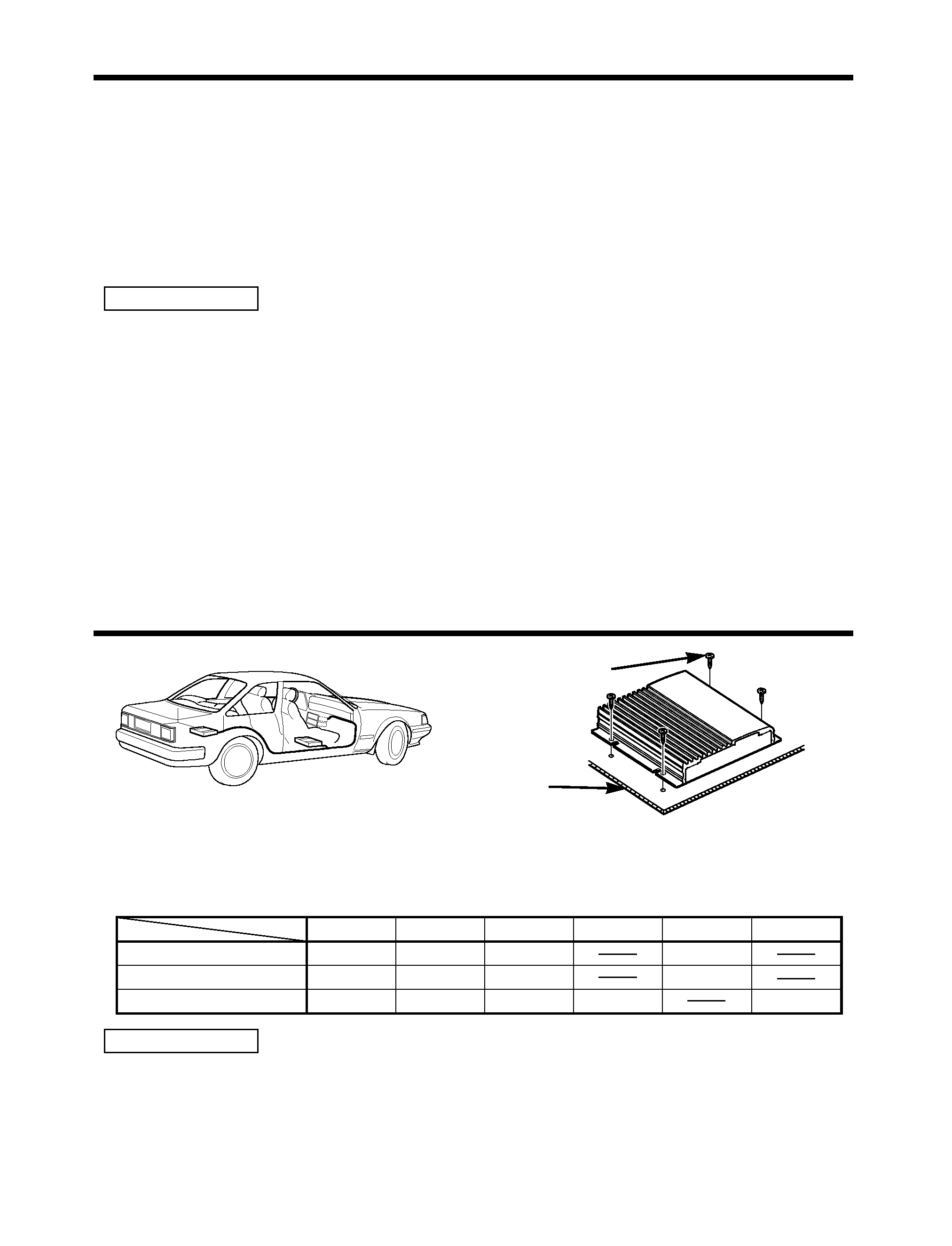
Installation procedure
Installation
· Since the power amplifier has no parts which require operation, it can be installed at a position
away from the driver's seat without any hindrances.
As generally accepted positions for its installation, places such as inside the trunk, etc. can be
considered.
· Use the extension cables. (Optional)
· Do not install the unit under the carpet. Otherwise heat build-up occurs and the unit may be
damaged.
· Install this unit in a location which allows heat to easily dissipate.
Once installed, do not place any object on top of the unit.
· Install the unit securely in a location that does not interfere with driving.
2CAUTION
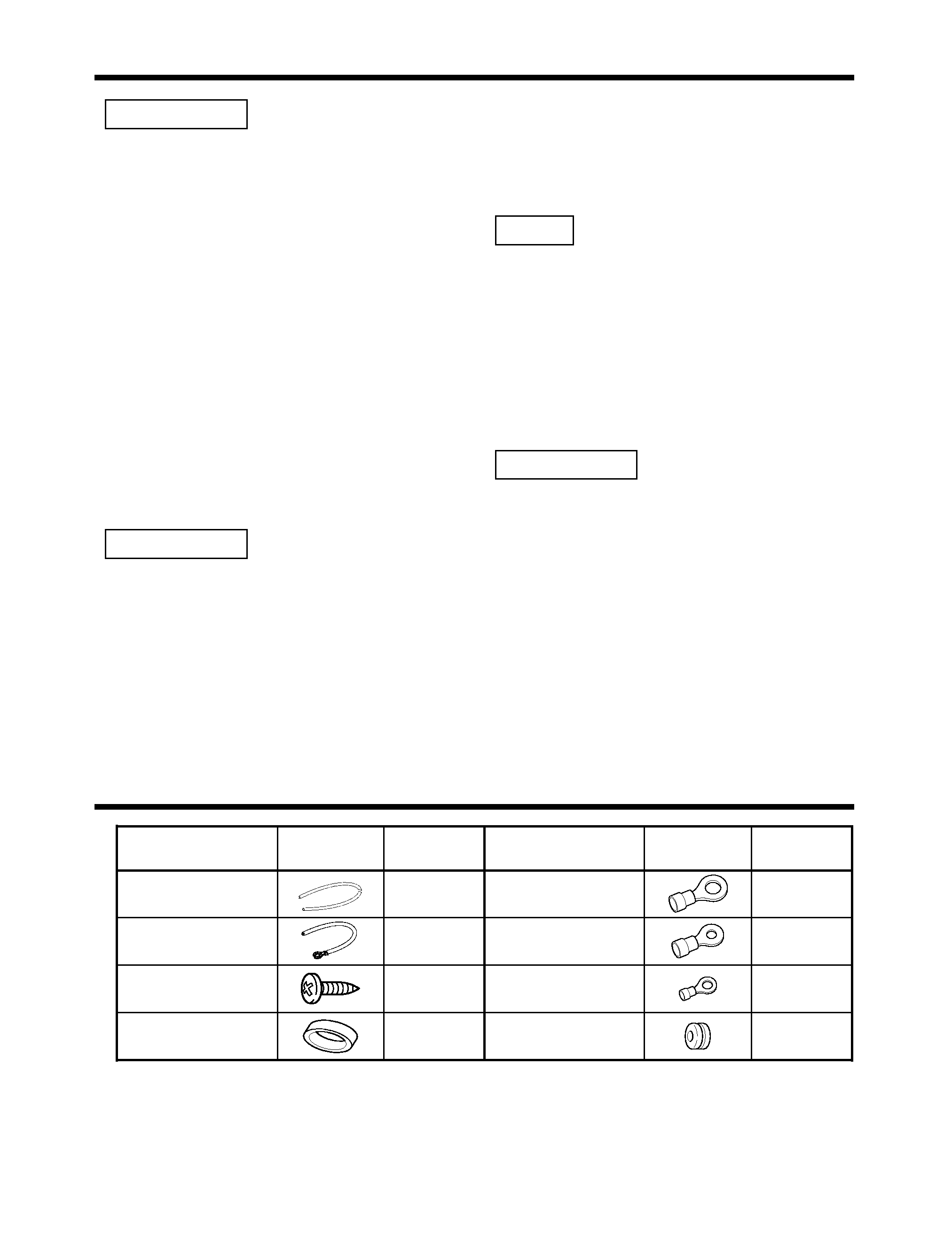
Installation board, etc.
(thickness : 15 mm or more)
Self-tapping screw
(ø4
× 16 mm)
CA-2SL
CA-12SL
CA-22SL
CA-52SL
RCA cable
CA-3WL
CA-13WL
CA-23WL
CA-53WL
RCA cable (ø7mm)
CA-5W
CA-15W
CA-25W
CA-45W
CA-65W
RCA cable (ø12mm)
0.5m
1m
2m
4m
5m
6m
Type
Length
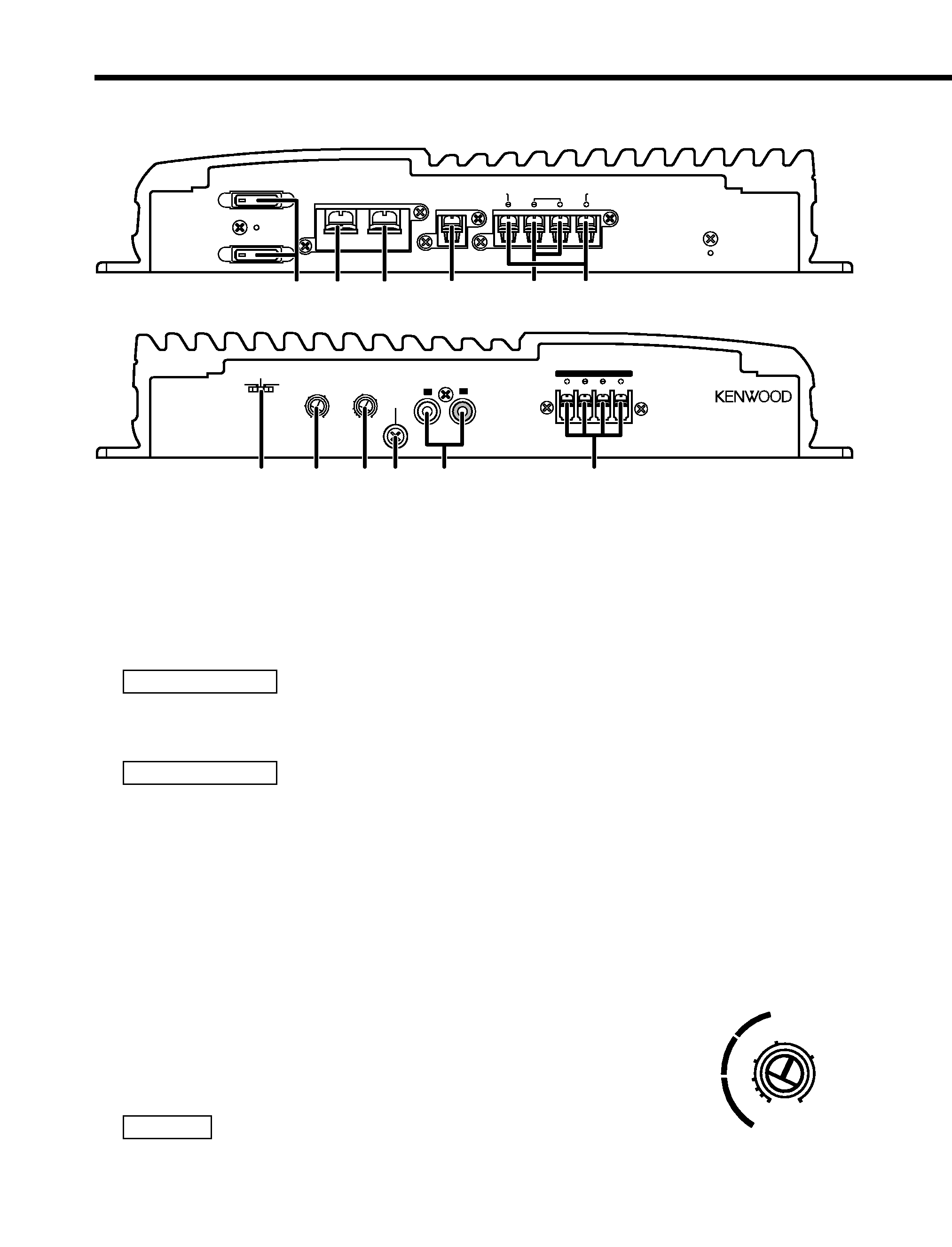
1. Remove the ignition key and disconnect the negative - terminal of the battery to prevent
short circuits.
2. Set the unit according to the intended usage.
3. Connect the input and output cables of the units.
4. Connect the center unit and this unit according to the required application.
5. Connect the speaker cables and sigma servo feed back cables.
6. Connect the power cable, power control cable and grounding cable following this order.
7. Install the unit in the car.
8. Connect the negative - terminal of the battery.
9. Turn power ON and ensure that sound is output normally.
· If sound is not output normally, immediately turn power off and check connections. Be sure to
perform the sigma servo connection correctly.
· Be sure to make correct connections of the sigma servo terminals.
· Be sure to turn the power off before changing the setting of any switch.
· If the fuse blows, check cables for shorts, then replace the fuse with one of the same rating.
· Check that no unconnected cables or connectors are touching the car body. Do not remove
caps from unconnected cables or connectors to prevent short circuits.
· Connect the speaker cables to appropriate speaker connectors separately. Sharing the
negative cable of the speaker or grounding speaker cables to the metal body of the car can
cause this unit to fail.
· After installation, check that the brake lamps, winkers, and wipers work properly.
2CAUTION
background image
4
Controls
Operations of the following control and switches are required in accordance with
the center unit and speakers connected with this unit.
POWER IN
FUSE(20A)
BATT
GND
FUSE(20A)
P.CON(REMOTE)
SPEAKER OUTPUT
1 2 3
45
6
MONO
POWER AMPLIFIER
L
25Hz
15Hz
INFRASONIC
OFF
INPUT
SENSITIVITY(V)
LPF
FREQUENCY(Hz)
GND
R
LINE IN
0.3
0.5
1
2
3
4
50.2
150
100
70
50
200
LEFT
RIGHT
SPEAKER LEVEL INPUT
@
7
8 9 0 !
20
20
SERVO
SERVO
1 FUSE (20 A
× 2)
2 Battery terminal
3 Ground terminal
4 Power control (REMOTE) terminal
5 Speaker output terminals
As this unit accepts speakers with a minimum impedance of 2 ohms, connect speakers with
2-ohm or higher impedance to these terminals.
The rated input of the speakers should be no less than the maximum output of the amplifier.
Otherwise malfunction may result.
6 SIGMA SERVO FEED BACK terminals (See p.8)
Be sure to make proper connections to the SIGMA SERVO FEED BACK terminals. Incorrect
connection may result in lack of sound output or other malfunctions.
7 INFRASONIC FILTER switch
Ultralow frequencies that cannot be reproduced even by a subwoofer speaker do not become
sound but become unnecessary oscillations, which affect the sound by causing distortion,
etc. Setting this switch to "15 Hz" or "25 Hz" cuts the frequencies below the respective
frequency.
This improves the reproduction performance of the speakers by eliminating unnecessary
oscillations which will not become sound.
8 LOW PASS FILTER FREQUENCY control
This control adjusts the frequency band output from this unit.
9 INPUT SENSITIVITY control
Set this control according to the pre-output level of the center unit
connected with this unit, or to the maximum power output of the
genuine-accessory car stereo.
Use the diagram on the right as a guide.
For the pre-output level or the maximum power output, refer to the
"Specifications" in the instruction manual of the center unit.
NOTE
2CAUTION
2CAUTION
0.3
0.2
0.5
1
2
3
4
5 (V)
(W)
25
15
10
background image
0 RCA cable ground lead terminal
! LINE IN terminal
@ Speaker level input terminals
s Power indicator:
When the power is turned on, the Power indicator lights.
If the Power indicator does not light when the power is turned on, the
protection function may be activated. Check whether there is any
indication of trouble.
s The protection function is activated in the following
situations:
This unit is equipped with a protection function for protecting this unit
and your speakers from various accidents or problems that can occur.
When the protection function is triggered, the Power indicator goes off
and the amplifier stops operating.
· A speaker cable may be short-circuited.
· A speaker output may be in contact with the ground.
· The temperature of the internal parts may be higher than 120°C (248°F).
· The sigma servo connection may be erroneous.
· The fuse of this unit may be blown.
· The unit may be malfunctioning and sending DC signal to the speaker output.
· The grounding cable of this unit may not be connected with a metallic part which is
electrically connected with the negative terminal of the battery.
· The power control cable may not be connected to this unit.
· The grounding cable of the center unit (cassette receiver, CD receiver, etc.) may not be
connected with a metallic part which is electrically connected with the negative terminal of
the battery.
5
Power indicator
Power indicator

Reviews

There are no reviews of this manual yet.