KENWOOD DVR-8100 Service Manual

Cover page of KENWOOD DVR-8100 Service Manual

Service Manual for KENWOOD DVR-8100, downloadable as a PDF file.

We also have owner's manual to this model.

Manual details

  • Immediate download after payment.
  • Delivered as a PDF file.
  • The manual has 33 pages
  • File size: 2.76 MB
  • Available language versions: English
  • Different language versions may vary sligthly in file size and page count.

We guarantee that...

  • our manuals are complete,
  • the manual includes circuit diagrams,
  • our manuals are checked with antivirus,
  • We'll issue refund if the manual is damaged, incomplete or unreadable (our refund policy)

Sample pages

Thumbnail of page 1Thumbnail of page 2Thumbnail of page 3Thumbnail of page 4
Thumbnail of page 5Thumbnail of page 6Thumbnail of page 7Thumbnail of page 8
Thumbnail of page 9
background image
70%
DVD / AV RECEIVER
DVR-8100
SERVICE MANUAL
(DVT-8100)
© 2002-9 PRINTED IN KOREA
B51-5824-00 (K/K) 1836
VOLUME CONTROL
STANDBY
ON
POWER
INPUT
VOLUME CONTROL
PHONES
ON SCREEN
TOP MENU
MENU
ACTIVE EQ
SKIP
¢
4
8
7
MULTI CONTROL
/ ÷ ENTER
23
5
£
0
/
OFF
DEC cabinet *
(A60-)
DEC crystal
(B10-3932-08)
ANTENNA
SAT / CABLE
IN
DVD COMPONENT
VIDELO OUT
S-VIDEO
VIDEO
Y
CB
CR
VCR
COAXIAL
OPTICAL
IN
OUT
DIGITAL
OUT
SAT/CABLE
MON.
MON.
OUT
SAT/
CABLE
SAT/
CABLE
OUT
VCR
DIGITAL IN
SAT/CABLE
VCR
DIGITAL IN
IN
IN
OUT
VCR
IN
IN
OUT
VCR
BIT STREAM
/PCM
(
(
Pun cover
(A01-3881-08)
In compliance with Federal Regulations, following are repro-
duction of labels on, or inside the product relating to laser
product safety.
KENWOOD Corp. certifies this equipment conforms to DHHS
Regulations No.21 CFR 1040. 10, Chapter 1, subchapter J.
DANGER : Laser radiation when open and interlock defeated.
AVOID DIRECT EXPOSURE TO BEAM.
Caution : No connection of ground line if disassemble
the unit. Please connect the ground line on
rear panel, PCBs, Chassis and some others.
DEC button
(B09-0907-08)
DEC button
(K29-8266-08)
DEC door tray
(A29-1214-08)
MLD clamp
(J42-0350-08)
Tuner module *
(W02-)
Conn-spe terminal
(E70-0165-08)
Con phono socket
(E63-1268-05)
DEC cap input
(B09-0904-08)
Phone jack
(E11-0957-08)
DEC knob(VOLUME)
(K29-8262-08)
DEC button
(B09-0905-08)
Con phono socket
(E63-1310-08)
Wire-MCRDM *
(E30-)
* Refer to parts list on page 24.
DEC button
(B09-0908-08)
DEC button
(B09-0906-08)
DEC knob multi
(K29-8263-08)
Con phono socket
(E56-0052-08)x2
Con phono socket
(E63-1309-08)x2
IC-Remote
(W02-2717-05)
IC-Remote
(W02-2716-05)x2
Con phono socket
(E63-1269-05)x3
background image
The marking of products using lasers (For countries other than U.S.A., U.S.-Military and Canada)
The marking this product has been clas-
sified as Class 1. It means that there is no
danger of hazardous radiation outside
the product.
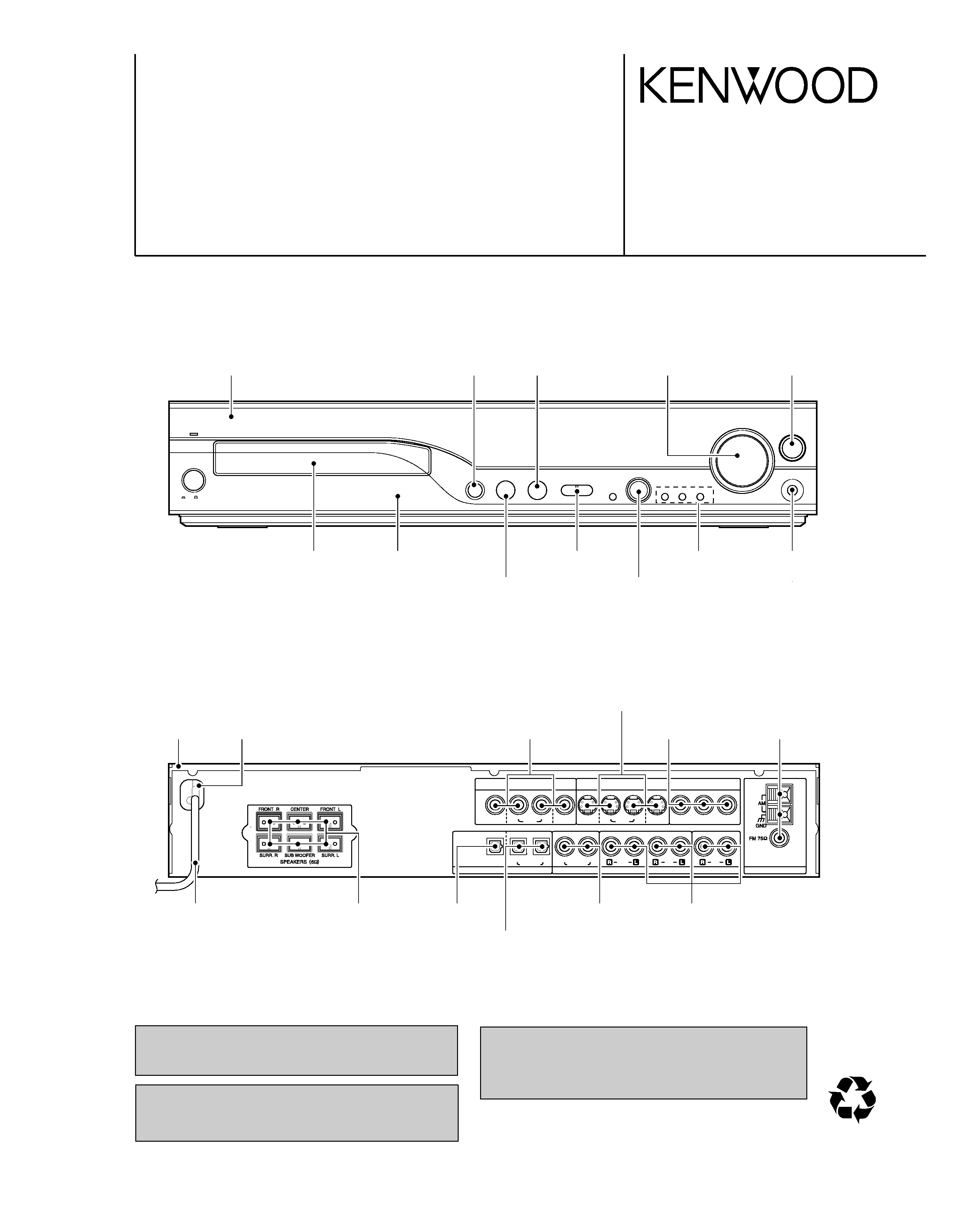
Location: Back panel
CLASS 1
LASER PRODUCT
CAUTION
INVISIBLE LASER RADIATION
WHEN OPEN. DO NOT STARE
INTO BEAM OR VIEW DIRECTLY
WITH OPTICAL INSTRUMENTS.
CAUTION
VISIBLE LASER RADIATION
WHEN OPEN. DO NOT
STARE INTO BEAM.
Inside this laser product, a laser diode classi-
fied as Class 2 laser radiation is contained as
alerted by the internal caution label shown
above. Do not stare into beam.
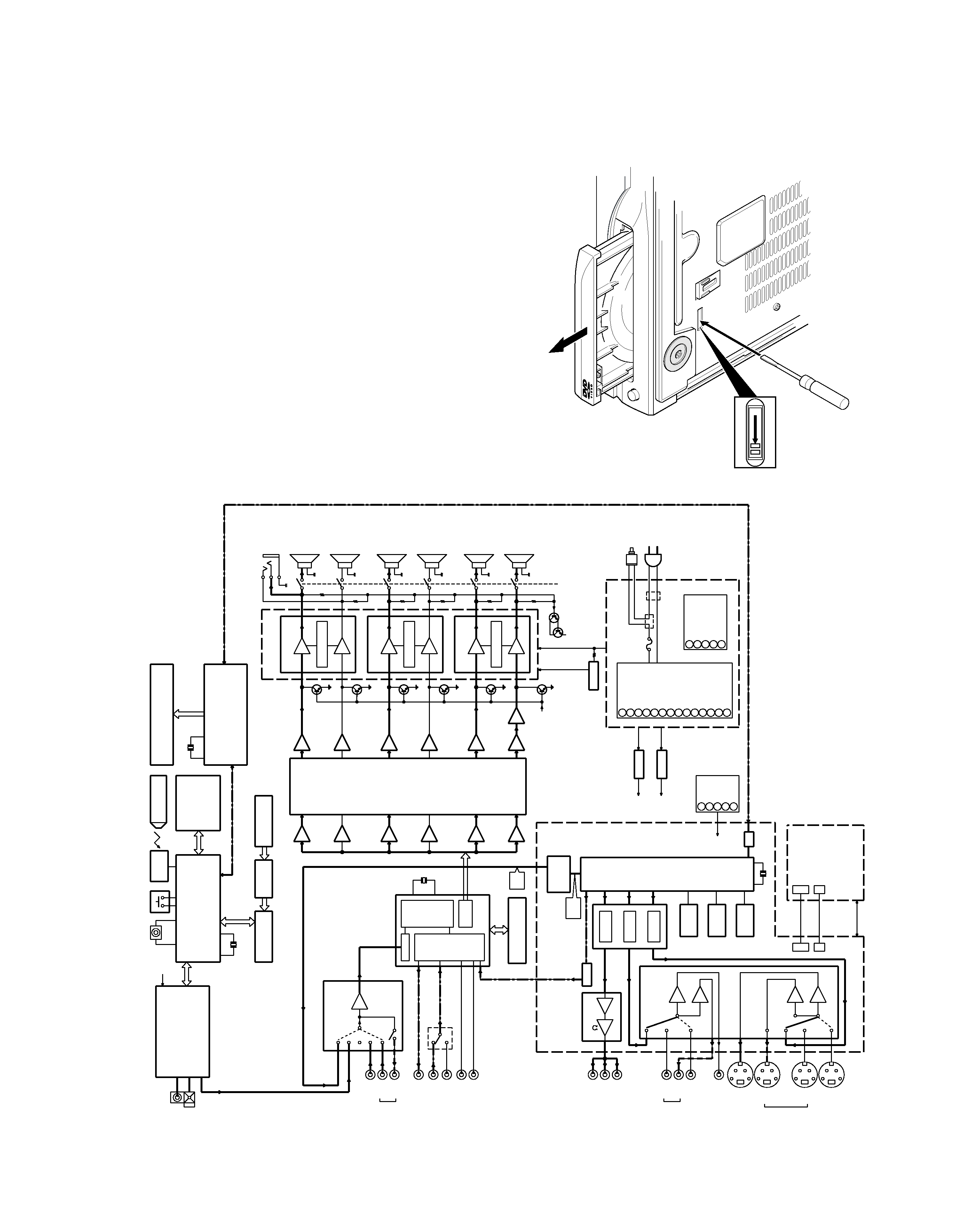
Location: DVD laser pick-up unit cover inside
this product
Inside this laser product, a laser diode classified as Class
3A laser radiation is contained as alerted by the internal
caution label shown above. Do not stare into beam or
view directly with optical instruments.
Location: CD laser pick-up unit cover inside this product
Operation to reset
The microcomputer may fall into malfunction (impossibility
to operate, erroneous display, etc.) when the power cord is
unplugged while power is ON or due to an external factor. In
this case, execute the following procedure to reset the
microcomputer and return it to normal condition.
Please note that resetting the microcomputer clears the con-
tents stored in and returns and to condition when it left the
factory.
Set the POWER switch to ON (set to Standby
mode). Then press the
key,
key and STOP
key in this order.
System
Speakers
DVR-8100
KSW-8100 (Left speaker, right speaker, center speaker, surround speakers and subwoofer)
Speaker model names
Note related to transportation and movement
Before transporting or moving this unit, carry out the
following operations.
1 Remove the disc from the unit.
2 Press the 6 key.
3 Wait a few seconds and turn the unit OFF.
Manufactured under license from Dolby Laboratories.
"DOLBY", "Pro Logic" and the double-D symbol are
trademarks of Dolby Laboratories.
"DTS" and "DTS Digital Surround" are trademarks of
Digital Theater Systems, Inc.
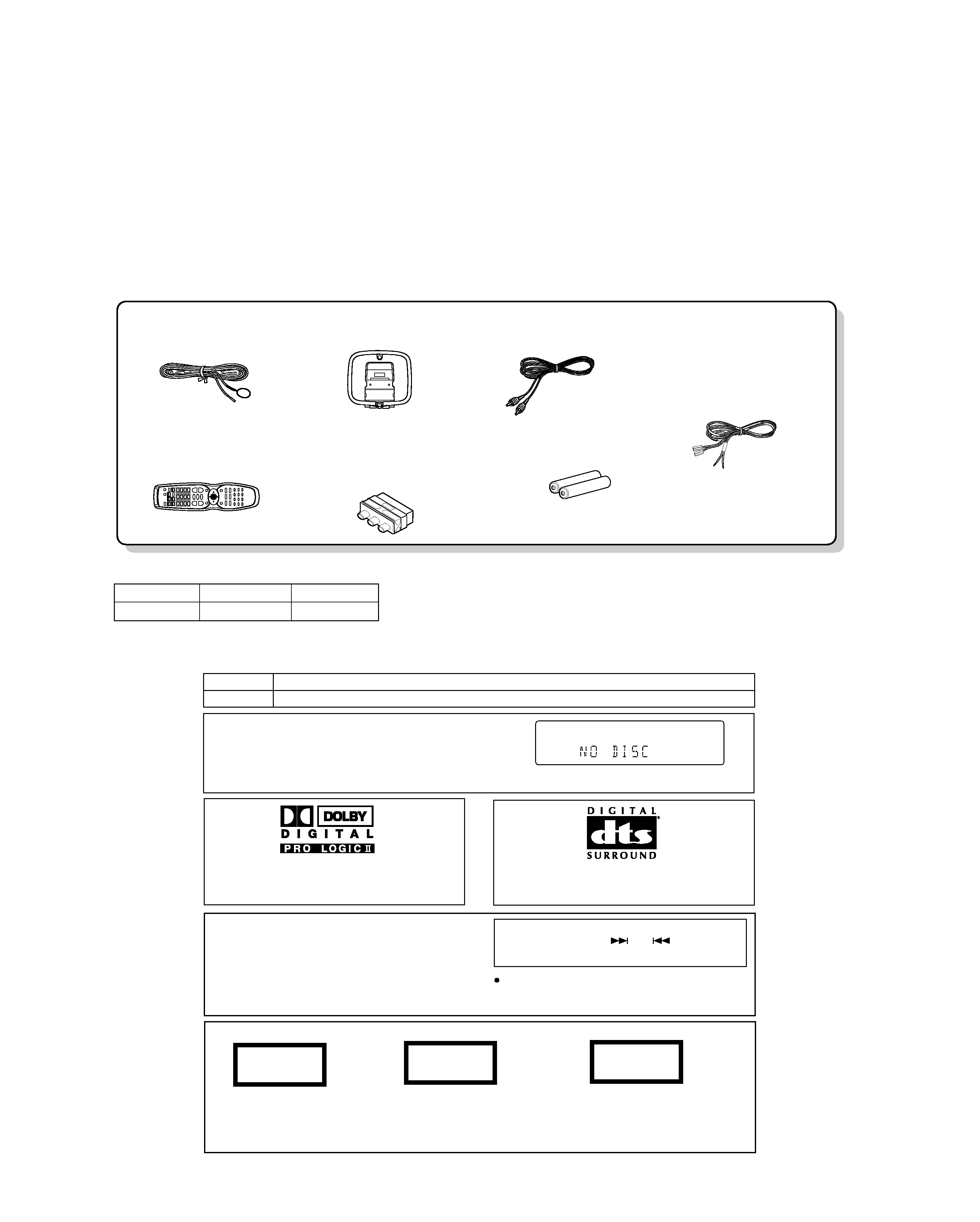
FM indoor antenna (1)
(T90-0882-08)
Loop antenna (1)
(T90-0896-08)
Remote control unit (1)
(A70-1600-08): X
(A70-1601-08): ET
Batteries (R6/AA) (2)
Video cord (1)
(E30-1427-05)
SCART plug adaptor (1)
(Europe and U.K. only)
(E69-0012-05)
Speaker cords (6)
(E30-7265-08): RD
(E30-7286-08): WH
(E30-7285-08): VT
(E30-7283-08): GN
(E30-7269-08): GY
(E30-7284-08): BL
DVR-8100
2
CONTENTS / ACCESSORIES / CAUTIONS
CONTENTS / ACCESSORIES / CAUTIONS ............. 2
DISASSEMBLY FOR REPAIR....................................3
BLOCK DIAGRAM ......................................................3
CIRCUIT DESCRIPTION ............................................4
ADJUSTMENT ..........................................................14
INTERCONNECTION DIAGRAM .............................15
PC BOARD .............................................................. 16
SCHEMATIC DIAGRAM .......................................... 23
EXPLODED VIEW ....................................................33
PARTS LIST..............................................................34
SPECIFICATIONS ......................................Back cover
Contents
Accessories
Cautions
SYSTEM
MAIN UNIT
SPEAKER
DVT-8100
DVR-8100
KSW-8100
SYSTEM CONFIGURATION
background image
DVR-8100
3
DISASSEMBLY FOR REPAIR / BLOCK DIAGRAM
How to open the tray if it does not come out.
1. Insert a flat driver in the drawing through the hole on the loading
chassis bottom and pull the lever down.
2. Pull out the tray frontward by hand when it comes just out.
DISASSEMBLY FOR REPAIR
BLOCK DIAGRAM
IC15
IC15
IC13
IC13
IC14
IC14
IC23
BD381
1
AUDIO
SOUND
PROCESSOR
CONTROL
T
O
NE
&
VOLUME
IC19
IC702
IC703
IC702
IC701
IC701
PROTECTION
T
A2022
IC501
PROTECTION
T
A2022
IC502
PROTECTION
T
A2022
IC503
K500
K500
FRONT/L
SPKR
SPKR
FRONT/R
K501
K501
SURROUND/R
SPKR
SPKR
SURROUND/L
WOOFER
SPKR
K502
K502
SPKR
CENTER
Q513-516
HP51
HEAD-
PHONE
AM
FM
ANT
TUNER
MODULE
FM/AM
SA
T/CABLE
IC23
BD381
1
IN
OUT
AUDIO
SOUND
PROCESSOR
VCR
AUDIO
MAIN
u-COM
CXP82860
IC22
ENCODER
VOLUME
MA
TRIX
KEY
VIDEO
P
A
R
T
SUPPL
Y
P
A
R
T
DSP
P
A
R
T
TUNER
P
A
R
T
AUDIO
P
A
R
T
MAIN
AMP
P
A
R
T
RM51
RMC
SENSOR
COMMANDER
IC9
AUDIO
DSP
CS49326
74VHC574
IC1/IC2
EP-ROM
IC5
A
T27L
V020A
DIGIT
AL
SA
T/C
IN
OPTICAL
OUT
VCR
IN
IC3
SA
T/C
COAX
IN
VCR
IN
IC7
AK4586
74VHC157
IC8
74VHCT244
LEVEL
CONVER
TER
COMPONENT
Cr
Y
OUTPUT
Cb
VIDEO
MM1540A
IC68
R/O
SA
T/CABLE
VCR
P/B
R/O
P/B
VCR
MONIT
OR
C-VIDEO
MONIT
OR
IC70
LA79510E
S-VIDEO
SA
T/CABLE
Y/C
CVBS
Cy/Cb/Cr
IC61
STI5519
MPEG
IC
64M
SDRAM
IC63
8MB
FLASH
IC66
24C02
EEPROM
IC62
TC5E
SPDIF
IC84
D/A
CONV
.
AUDIO
L/R
PCM1748
D
ATA
PCM
L/R
DVD
IC51
FRONT
u-COM
FL51
FIP
15-BT
-85GNK
CN4
CN5
1L1
12HI
KIA7812
IC24
IC25
KIA7912
KIA7805
IC505
SIO
POWER
SW
IC703
CXP82832
SUB
9dB
FL
AMP
FR
AMP
9dB
RS
AMP
LS
AMP
9dB
9dB
CT
AMP
SW
AMP
9dB
9dB
15.5dB
SW
AMP
8.5dB
8.5dB
8.5dB
8.5dB
8.5dB
FL
AMP
FR
AMP
LS
AMP
RS
AMP
CT
AMP
FL
AMP
FR
AMP
RS
AMP
LS
AMP
CEN
AMP
SW
AMP
MUTE
PROTECTION
SPKR
RL
Y
+12V
DA
T
A
IN
CLK
DA
T
A
OUT
PLL
CE
TUNED
MUTE
L/R
AUDIO
OUT
BUFFER
TUNER
DVD
L/R
-6dB
0dB
S500
RMC
X2
10MHz
2ch
ADC
TX
RX2
RX4
RX3
RX1
DIR
AUDIO
I/F
6ch
DAC
OUT
AUDIO
-9dB
6ch
12.288MHz
X1
OSC
SUB
DA
T
A
IN/OUT
CLK
75
DRIVER
GAIN
6dB
6dB
6dB
6dB
6dB
27MHz
CN64
14
13
9
10
11
12
2
4
5
6
7
8
3
1
5
2
4
3
1
+6V
GND
5V
STBY
-5V
14.5V
I2C
PROGRAM
STREAM
RECEPTION
/MOT
OR
CONTROL
(OPEN/CLOSE)
MOT
OR
CONTROL
+12V
DVCC
DA
T
A/CLK
+5V
A
RESET
+5VD
+3.3VD
X501
10MHz
RESONA
T
O
R
-FL
P
A
R
T
5
1
3
4
2
FL5V
FL
GND
GND
5V
STBY
-14.5V
6V
14.5V
GND
POWER
CHECK
5V
STBY
-30V
FL
GND
GND
STBY
ON
14.5V
+6V
5V
STBY
-5V
GND
208-264V
50/60Hz
3.15A
+12V
+14.5V
-12V
-14.5V
CONTROL
CONTROL
CIRCUIT
5VBIAS
+30V
-30V
DVD-RX
DVD-RESET
DVD-TX
SIO
SW
AMP
8.5dB
DIGIT
AL
AMP
MECHA
&
F/E
MPEG
BOARD
SMPS
DVR-8100
background image
DVR-8100
4
CIRCUIT DESCRIPTION
Pin No.
Pin Name
I/O
Pin Description
PIOs and communication
1
PIO2(5) RGB SEL(BLANK)
I/O
RGB sel (blank). unused
2
PIO2(6) VIDEO MUTE
I/O
Video mute control.
3
PIO2(7) 16: 9 INDICATOR
I/O
16 : 9 indicator (unused).
6
PIO3(0) SCART H (TV/AUX)
I/O
Unused.
7
PIO3(1)
I/O
Unused.
8
PIO3(2)
-
CSB (unused).
9
PIO3(3)
-
SDIN (unused).
10
PIO3(4) IR REMOCON
I/O
Unused.
11
PIO3(5)
-
SCLK (unused).
12
PIO3(6)
I/O
Unused.
13
PIO3(7) DVD RESET
I/O
Power- on reset of front-end module.
Front-end
16
B DATA
I
I2S Data
17
B BCLK
I
I2S Bit clock
18
B FLAG
I
I2S Error flag
19
B SYNC
I/O
I2S Sector / ABS time
Reserved
20
B WCLK
I/O
Unused.
21
B V4
I/O
Unused.
22
NRSS OUT
I/O
Unused.
23
VDD RGB
-
Supply voltage for RGB (+3.3VA).
24
VSS RGB
-
GND
Video DAC
25,26,27
B/G/R (OUT)
O
B/G/R signal outputs.
28
V REF RG
I
Reference voltage input for DAC RGB.
29
I REF RG
I
Reference current input for DAC RGB.
30
VDD YCC
-
Supply voltage for YCC (+3.3VA).
31
VSS YCC
-
GND
32~34
Y/C/CV (OUT)
O
Y/C/CV signal outputs.
35
V REF YCC
I
Reference voltage input for DAC YCC.
36
I REF YCC
I
Reference current input for DAC YCC.
PIOs and communication
39
PIO4(0)HP MUTE
-
Unused.
40
PIO4(1)
-
Unused.
41
PIO4(2)
-
Unused.
42
PIO4(3) DAC RESET
-
Unused.
43
PIO4(4) PLL CS
-
Unused.
44
PIO4(5) DAC CLOCK
O
DAC clock output.
45
PIO4(6) DAC DATA
O
DAC data output.
46
PIO4(7) DAC CS
O
DAC chip select.
Audio DAC
48
VDD PCM
-
Supply voltage for PCM (+3V3).
49
VSS PCM
-
Ground for PCM.
51
DAC SCLK
O
DAC over sampling clock.
52
DAC PCMOUT0
O
DAC PCM data out 0.
53
DAC PCMOUT1
O
DAC PCM out 1 (unused).
54
DAC PCMOUT2
O
DAC PCM out 2 (unused).
55
DAC PCMCLK
O
DAC PCM clock.
56
DAC LRCLK
O
DAC PCM Left/Right clock.
57
SPDIF OUT
O
Audio digital data output.
Shared memory interface
58~63
SMI ADR(4~9)
O
SDRAM address bus.
66~69
SMI ADR(3~0)
O
SDRAM address bus.
1. Pin Description of MPEG Processor IC (DVD & VIDEO IC61)
background image
DVR-8100
5
CIRCUIT DESCRIPTION
Pin No.
Pin Name
I/O
Pin Description
70~73
SMI ADR(10~13)
O
SDRAM address bus.
74
SMI CS(0)
O
Chip select bank 0.
75
SMI CS(1)
-
Unused.
76
SMI RAS
O
SDRAM RAS
77
SMI CAS
O
SDRAM CAS
78
SMI WE
O
SDRAM write enable.
79
SMI DQML
O
DQ MASK enable low.
80
SMI DQMU
O
DQ MASK enable up.
82
SMI CLKIN
I
SDRAM clock input.
84~93
SMI DATA(0~9)
I/O
SDRAM data bus.
95
SMI CLKOUT
O
SDRAM clock out.
97~102
SMI DATA(10~15)
I/O
SDRAM data bus.
Reserved
103
ADC SCLK
I/O
ADC digital audio port clock (unused).
104
ADC LRCLK
I/O
ADCsample rate clock (unused).
105
ADC DATA
I
ADC digital audio data input (unused).
106
ADC PCMCLK
O
Crystal input or master clock input (unused).
JTAG
109
TRST
I
Test reset from emulator module.
110
TMS
I
Test mode select.
111
TDO
O
Test data out to emulator module.
112
TDI
I
Test data input from emulator module.
113
TCK
I
Test clock input from emulator module.
Timers
114
PWM2
I/O
Unused.
115
PWM1
I/O
ROM boot option port (voltage low = emulator booting).
116
PWM0
I/O
Unused.
EMI Interface
117
CPU OE
I/O
Flash ROM output enable.
118
CPU PRO CLK
O
SDRAM clock (unused).
Clock & Reset
120
PIX CLK
I
27MHz main clock input.
122
VDD PLL
-
Supply voltage for PLL (+3V3).
123
VSS PLL
-
Ground for PLL.
124
RESET
I
Chip reset input.
Interrupt
125
IRQ(2)
I
Interrupt request 2 from front-end module.
126
IRQ(1)
I
Unused.
127
IRQ(0)
I
Unused.
EMI Interface
128
CPU BE(0)
O
BYTE 0 Enable
129
CPU BE(1)
O
BYTE 1 Enable
130
CPU RW
O
Unused.
131
CPU WAIT
I
Wait state (connected to ground).
132
CPU CE(3)
O
Flash ROM chip select.
133
CPU CE(2)
O
Flash ROM down-load JIG module select.
134
CPU CE(1)
O
Unused.
135
CPU CE(0)
O
Unused.
138
CPU RAS1
I/O
Unused.
139
CPU CAS0
O
Unused.
140
CPU CAS1
O
Unused.
141~148
CPU DATA(0~7)
I/O
Flash ROM data input/output (0~7).
151~158
CPU DATA(8~15)
I/O
Flash ROM data input/output (8~15).
161~170
CPU ADR(1~10)
O
Flash ROM address (1~10).
173~181
CPU ADR(11~19)
O
Flash ROM address (11~19).

Reviews

There are no reviews of this manual yet.