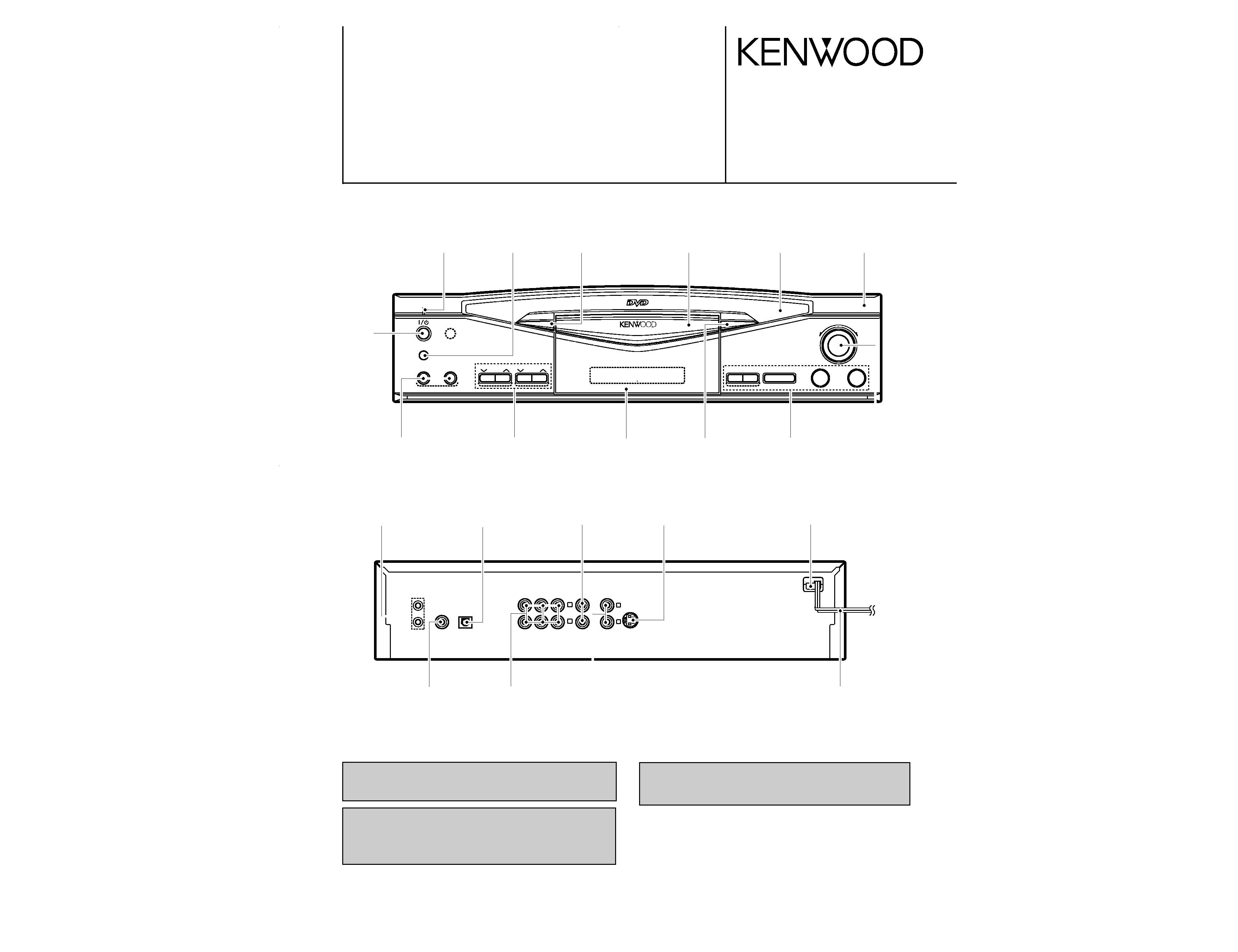
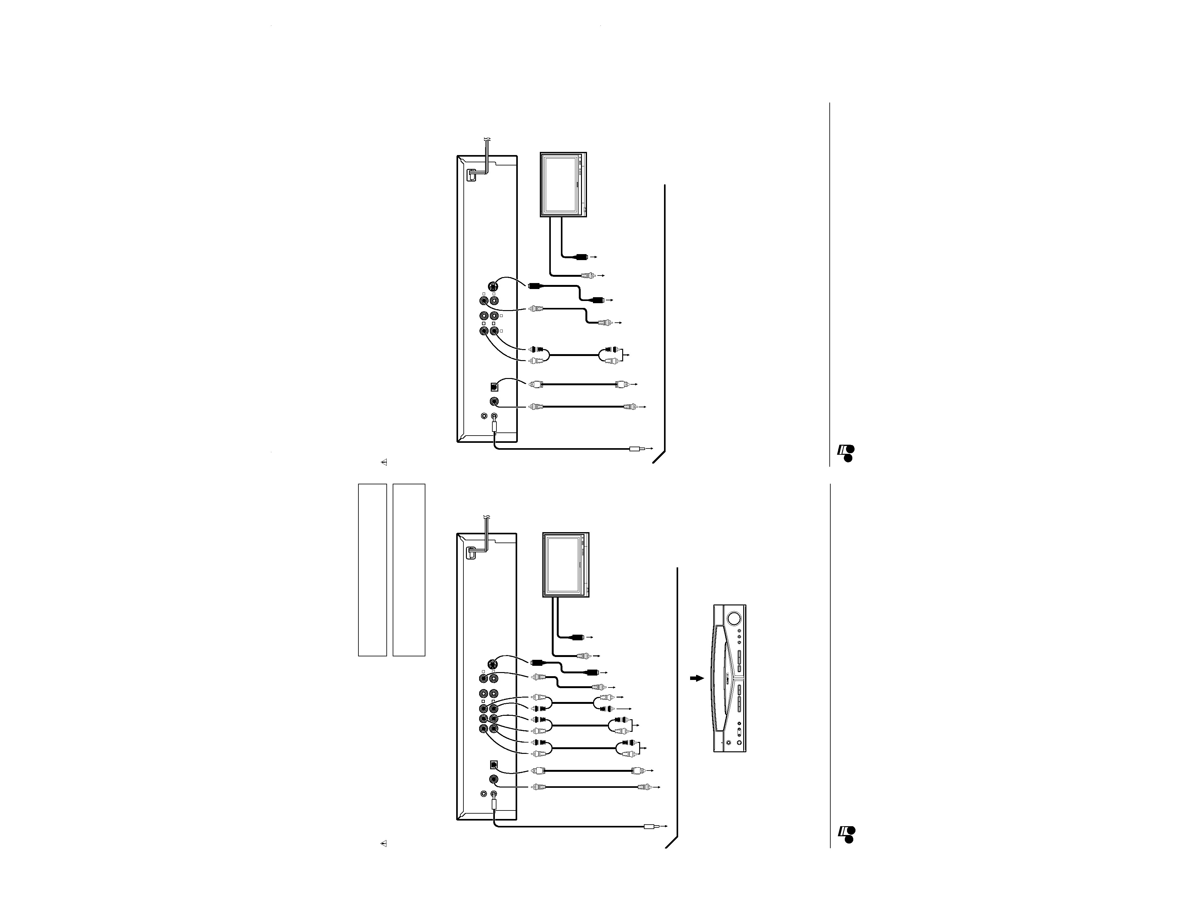
KENWOOD DVKS701 Service Manual

Cover page of KENWOOD DVKS701 Service Manual

Service Manual for KENWOOD DVKS701, downloadable as a PDF file.

Manual details

  • Immediate download after payment.
  • Delivered as a PDF file.
  • The manual has 36 pages
  • File size: 3.04 MB
  • Available language versions: English
  • Different language versions may vary sligthly in file size and page count.

We guarantee that...

  • our manuals are complete,
  • the manual includes circuit diagrams,
  • our manuals are checked with antivirus,
  • We'll issue refund if the manual is damaged, incomplete or unreadable (our refund policy)

Sample pages

Thumbnail of page 1Thumbnail of page 2Thumbnail of page 3Thumbnail of page 4
Thumbnail of page 5Thumbnail of page 6Thumbnail of page 7Thumbnail of page 8
Thumbnail of page 9
background image
In compliance with Federal Regulations, following are reproduc-
tions of labels on, or inside the product relating to laser product
safety.
KENWOOD-Crop. certifies this equipment conforms to DHHS
Regulations No. 21 DFR 1040. 10, Chapter 1, Subchapter J.
DANGER : Laser radiation when open and interlock defeated.
AVOID DIRECT EXPOSURE TO BEAM
Caution : No connection of ground line if disassemble the
unit. Please connect the ground line on rear
panel, PCBs, Chassis and some others.
NOTE : Please replace the mechanism PCB
(W02-266x-05) with new one, if it is
malfunction.
CD/VIDEO-CD/DVD PLAYER
DV-K751/S701
SERVICE MANUAL
© 1998-8/B51-5468-00 (K/K) 3547
Illust. is DV-K751.
* Refer to parts list on page 33.
73
¢
4
¡
1
MIC 2
MIC 1
POWER
- ON ­ OFF
ON / STANDBY
SHUTTLE
0
w
8
/
MIC LEVEL
MIC 1
MIC 2
FL
DISPLAY
(PCM/BIT STREAM)
COAXIAL
OPTICAL
DIGITAL OUTPUT
CENTER
S VIDEO
OUTPUT
VIDEO
OUTPUT
MIX LINE
OUTPUT
SUB
WOOFER
SURROUND
FRONT
6CH. OUTPUT
L
R
1
2
SYSTEM
CONTROL
Knob
(K29-6835-22)
Indicator
(B12-0311-04)
AC power cord *
(E30-)
Phono jack
(E63-1064-05)
Phono jack
(E63-1052-05)
Power cord bushing
(J42-0083-05)
Phono jack
(E11-0366-05)
Knob
(K27-2249-04)
Knob
(K29-6835-22)
Phono jack
(E63-0128-05)
Phono jack
(E63-0122-05)
Cylindrical receptacle
(E56-0014-05)
Oscillating module
(W02-1114-05)
Dressing panel
(A21-3728-03)
Knob
(K29-6677-03)
Panel *
(A60-)
Dressing panel
(A21-3627-12)
Miniature phone jack
(E11-0188-05)
Knob
(K29-6679-03)
Front glass
(B10-2386-12)
Knob
(K29-6835-22)
Knob
(K29-6945-04)
DV-K751(K)COVER1,1( 98.12.1215:04 y[W 2
background image
Audio
(E30-0505-05)
(E30-1427-05)
(E30-2365-05)
(E30-2733-05)
cord (Red, White) ...... (3)
Remote
(A70-1231-05): RC-D0703: M2T1E1
(A70-1243-05): RC-D0704: K
(A70-1244-05): RC-D0706: M1C1
Battery cover (A09-1105-05)
control unit ............. (1)
Batteries (R6/AA) ................. (2)
Digital cord (Orange) ......... (1)
Video cord (Yellow) .............. (1)
System control cord ......... (1)
AC
(E03-0115-05)
plug adaptor ............. (1)
Use to adapt the plug on the power cord to the shape
of the wall outlet.
(Accessory only for regions where use is necessary.)
DV-K751/S701
2
CONTENTS / ACCESSORIES
CONTENTS / ACCESSORIES ...................................2
CAUTIONS...................................................................3
CONTROLS .................................................................4
BLOCK DIAGRAM .......................................................8
CIRCUIT DESCRIPTION .............................................9
ADJUSTMENT .......................................................... 10
PARTS DESCRIPTIONS ...........................................12
PC BOARD ................................................................13
SCHEMATIC DIAGRAM ............................................17
EXPLODED VIEW .....................................................30
PARTS LIST...............................................................33
SPECIFICATIONS .....................................................43
Contents
Accessories
DV-K751(K)COVER1,1( 98.12.1215:04 y[W 3
background image
DV-K751/S701
3
CAUTIONS
Operation to reset
The microprocessor may fall into malfunction (impossibility to operate
erroneous display, etc.) when the power cord is unplugged while power
is ON or due to an external factor. In this case, execute the following
procedure to reset the microprocessor and return it to normal condi-
tion.
÷ Please note that resetting the microprocessor clears the contents
stored in, it returns the microprocessor to the condition when it left
the factory.
Perform the following operation.
1 Press the POWER key to the ON position.
2 Press the ON/STANDBY (
) key to ON.
3 Wait for a few seconds to ensure that the display shows "NO
DISC".
4 While holding the 7 key, press and hold the ON/STANDBY
(
) key until "INITIAL OK!" appears.
NO DISC
Note related to transportation and move-
ment
Before transporting or moving this unit, be sure to remove any
disc from it and carry out the following operation.
1. Press the POWER key to the ON position.
2. Press the ON/STANDBY (
) key to ON.
3. Wait a few seconds and verify that the display shown appears.
4. Set the POWER key to OFF.
Operation to reset
The microprocessor may fall into malfunction (impossibility to operate
erroneous display, etc.) when the power cord is unplugged while power
is ON or due to an external factor. In this case, execute the following
procedure to reset the microprocessor and return it to normal condi-
tion.
÷ Please note that resetting the microprocessor clears the contents
stored in, it returns the microprocessor to the condition when it left
the factory.
Perform the following operation.
1 Press the MAIN POWER key to the ON position.
2 Press the REMOTE POWER key to ON.
3 Wait for a few seconds to ensure that the display shows "NO
DISC".
4 While holding the 7 key, press and hold the REMOTE POWER key
until "INITIAL OK!" appears.
NO DISC
Note related to transportation and move-
ment
Before transporting or moving this unit, be sure to remove any
disc from it and carry out the following operation.
1. Press the MAIN POWER key to the ON position.
2. Press the REMOTE POWER key to ON.
3. Wait a few seconds and verify that the display shown appears.
4. Set the MAIN POWER key to OFF.
WITH ON/STANDBY KEY
WITH REMOTE POWER KEY
DV-K751(K)COVER1,1( 98.12.1215:04 y[W 6
background image
DV
-K751/S701
4
CONTROLS
73
¢
4
¡
1
MIC 2
MIC 1
POWER
- ON ­ OFF
ON / STANDBY
SHUTTLE
0
w
8
/
MIC LEVEL
MIC 1
MIC 2
FL
DISPLAY
1
6
8
3
2
4
5
7
0
!
@
#
$
%
^
DVD VCD CD
P.B.C.
DOLBY DIGITAL
RANDOM PROG.
STEREO
ANGLE
PCM
REPEAT ALL
LR
TITLE CHAPTER TRACK
A
B
· · · · · · · · · · · · · · ·
KARAOKE
9
POWER
- ON ­ OFF
Display / Main unit (DV-K751)
L, STEREO, R indicators
Character information display
Operation indicators
3 : Play
8 : Pause
DVD, VCD, CD indicators
Special playback related indicators
Display
VCD and CD related indicators
DVD related indicators
1 ON/STANDBY (
) key
Press to turn power of the unit from on to standby or vice versa.
2 Standby indicator
3 Remote control sensor
4 FL DISPLAY key
5 DVD indicator
Lights when a DVD disc is played.
6 Disc tray
7 Open/Close (0) key
8 SHUTTLE (1, ¡) keys
9 POWER (
POWER) key
Press to turn the power of the unit between the standby and off
modes.
0 MIC 1 and MIC 2 jacks
! MIC 1 level
up
:
down :
@ MIC 2 level
up
:
down :
# Skip down (4) / up (¢) keys
$ Still/Pause (
) key
% Stop (7) key
^ Play (3) key
* The panel
indications are
variable depending
on the area where
the nuit is
marketed.
About the standby mode
While the standby indicator is lit, a small amount of power is supplied to the system to back up the memory. This is called th
standby mode. Under that condition, the system can be turned ON by the remote control unit.
73
¢
4
¡
1
POWER
- ON ­ OFF
ON / STANDBY
SHUTTLE
0
w
8
/
TEXT
DISPLAY
ALL
INFO.
TITLE
SEARCH REPEAT
FL
DISPLAY
1
6
8
3
2
4
5
7
$
%
^
&
0 ! @ #
DVD VCD CD
P.B.C.
DOLBY DIGITAL
RANDOM PROG.
STEREO
ANGLE
PCM
MPEG
REPEAT ALL
LR
TITLE CHAPTER TRACK CD TEXT
A
B
· · · · · · · · · · · · · · ·
9
Display / Main unit (DV-S701)
L, STEREO, R indicators
Character information display
Operation indicators
3 : Play
8 : Pause
DVD, VCD, CD indicators
Special playback related indicators
About the standby mode
While the standby indicator is lit, a small amount of power is supplied to the system to back up the memory. This is called the
standby mode. Under that condition, the system can be turned ON by the remote control unit.
Display
VCD and CD related indicators
DVD related indicators
1 ON/STANDBY (
) key
Press to turn power of the unit from on to standby or vice versa.
2 Standby indicator
3 Remote control sensor
4 FL DISPLAY key
5 DVD indicator
Lights when a DVD disc is played.
6 Disc tray
7 Open/Close (0) key
8 SHUTTLE (1, ¡) keys
9 POWER key
Press to turn the power of the unit between the standby and off
modes.
0 TEXT DISPLAY key
! ALL INFO. key
@ TITLE SEARCH key
# REPEAT key
$ Skip down (4) / up (¢) keys
% Still/Pause (
) key
^ Stop (7) key
& Play (3) key
DV-K751(K)
COVER1,1(
98.12.12
15:04
y[W
7
background image
DV
-K751/S701
5
CONNECTIONS
(PCM/BIT STREAM)
COAXIAL
OPTICAL
DIGITAL OUTPUT
CENTER
S VIDEO
OUTPUT
VIDEO
OUTPUT
MIX LINE
OUTPUT
SUB
WOOFER
SURROUND
FRONT
6CH. OUTPUT
L
R
1
2
SYSTEM
CONTROL
OPTICAL IN/Optical fiber cable (commercially available)
Monitor TV
(commercially available)
DV-S701(OTHER AREA)/DV-K751
To wall AC
outlet
Notes
Notes
COAXIAL IN/Digital cord (75
coaxial) (provided)
AV CONTROL CENTER (sold separately) or
receiver (sold separately)
VIDEO OUT/Video cord (75
coaxial) (commercially available)
S-VIDEO IN
S-VIDEO OUT/S-VIDEO cord (commercially available)
VIDEO IN
CENTER IN/Audio cord (provided)
SUBWOOFER IN/Audio cord (provided)
FRONT L/R IN/Audio cord (provided)
SURROUND L/R IN/Audio cord (provided)
S-VIDEO IN/S-VIDEO cord (commercially available)
VIDEO IN/Video cord (75
coaxial) (provided)
Connect the cords and cables accordingto the jacks available on the connected AV receiver.
* If you want to use
the macro function
of a KENWOOD AV
CONTROLCENTER
(sold separately),
connect this player
to a wall AC outlet.
Be sure to set the
POWER switch on
the front panel of
this unit to OFF
when you are going
to leave the unit
unattended for
going out of the
house, etc.
Make connection as shown below. When connecting the
related system components, refer also to the instruction
manuals of the related components.
Caution: Do not plug in the power lead until all connec-
tions are completed.
1. Connect all cords firmly. If connections are loose, there could be loss of sound or noise produced.
2. When plugging and unplugging connection cords, be sure to first remove the power cord from the AC outlet. Plugging/unplugging
connection cords without removal of the power cord can cause malfunctions or damage to the unit.
The VIDEO OUTPUT jacks should be connected directly to the TV. Do
not connect them to the TV via a VCR. Otherwise the played video
may be disturbed due to the copy protection function.
Initial setup
Set initial setup [6. TV Aspect] according to the aspect ratio (4:3 or
16:9) of your TV.
SYSTEM CONTROL IN/System control cord (provided)
Stereo system
(commercially available)
* The connected components shown here are typical examples.
(PCM/BIT STREAM)
COAXIAL
OPTICAL
DIGITAL OUTPUT
S VIDEO
OUTPUT
VIDEO
OUTPUT
AUDIO
OUTPUT
L
R
1
1
2
2
SYSTEM
CONTROL
OPTICAL IN/Optical fiber cable (commercially available)
Monitor TV
(commercially available)
DV-S701(U.S.A.)
To wall AC
outlet
Notes
Notes
COAXIAL IN/Digital cord (75
coaxial) (provided)
VIDEO OUT/Video cord (75
coaxial) (commercially available)
S-VIDEO IN
S-VIDEO OUT/S-VIDEO cord (commercially available)
VIDEO IN
FRONT L/R IN/Audio cord (provided)
S-VIDEO IN/S-VIDEO cord (commercially available)
VIDEO IN/Video cord (75
coaxial) (provided)
Connect the cords and cables according to the jacks available on the connected AV receiver.
* If you want to use
the macro function
of a KENWOOD AV
CONTROLCENTER
(sold separately),
connect this player
to a wall AC outlet.
Be sure to set the
POWER switch on
the front panel of
this unit to OFF
when you are going
to leave the unit
unattended for
going out of the
house, etc.
Make connection as shown below. When connecting the
related system components, refer also to the instruction
manuals of the related components.
Caution: Do not plug in the power lead until all connec-
tions are completed.
1. Connect all cords firmly. If connections are loose, there could be loss of sound or noise produced.
2. When plugging and unplugging connection cords, be sure to first remove the power cord from the AC outlet. Plugging/unplugging
connection cords without removal of the power cord can cause malfunctions or damage to the unit.
SYSTEM CONTROL IN/System control cord (provided)
DV-K751(K)
COVER1,1(
98.12.12
15:04
y[W
10

Reviews

There are no reviews of this manual yet.