KENWOOD DVF-N7080-S Service Manual

Cover page of KENWOOD DVF-N7080-S Service Manual

Service Manual for KENWOOD DVF-N7080-S, downloadable as a PDF file.

Manual details

  • Immediate download after payment.
  • Delivered as a PDF file.
  • The manual has 19 pages
  • File size: 3.09 MB
  • Available language versions: English
  • Different language versions may vary sligthly in file size and page count.

We guarantee that...

  • our manuals are complete,
  • the manual includes circuit diagrams,
  • our manuals are checked with antivirus,
  • We'll issue refund if the manual is damaged, incomplete or unreadable (our refund policy)

Sample pages

Thumbnail of page 1Thumbnail of page 2Thumbnail of page 3Thumbnail of page 4
Thumbnail of page 5Thumbnail of page 6Thumbnail of page 7Thumbnail of page 8
Thumbnail of page 9
background image
DVD/VCD/CD PLAYER
DVF-N7080/N7080-S
SERVICE MANUAL
© 2004-9 PRINTED IN KOREA
B51-5924-00 (K/K) 776
70%
70%
In compliance with Federal Regulations, following are repro-
duction of labels on, or inside the product relating to laser
product safety.
KENWOOD Corp. certifies this equipment conforms to DHHS
Regulations No.21 CFR 1040. 10, Chapter 1, subchapter J.
DANGER : Laser radiation when open and interlock defeated.
AVOID DIRECT EXPOSURE TO BEAM.
Caution : No connection of ground line if disassemble
the unit. Please connect the ground line on
rear panel, PCBs, Chassis and some others.
YCB
CR
COMPONENT VIDEO
R
L
AUDIO
VIDEO
S VIDEO
OPTICAL COAXIAL
DIGITAL OUT
(BIT STREAM/PCM)
ETHERNET
COMPONENT VIDEO OUTPUT
AV
OUTPUT
Panel *
(A60-)
Front glass *
(B10-)
Knob *
(K29-)
Indicator
(B12-0480-04)
Power cord bushing
(J42-0349-05)
Metallic cabinet *
(A01-)
Pin jack
(E63-1352-05)
Pin jack
(E63-1351-05)
Pin jack
(E63-1353-05)
Knob *
(K29-)
Foot
(J02-1560-03)x4
Jack(others) *
(E68-)
AC power cord *
(E30-)
Rectangular receptacle
(E58-0063-05)
Oscillating module
(W02-2998-05)
Rectangular receptacle
(E58-0068-05)
Cylindrical receptacle
(E56-0055-05)
* Refer to parts list on page 20.
background image
Batteries(R6/AA) ...(2)
Audio cord (Red, White) ...(1)
(E30-0505-05)
Video cord (Yellow) ...(1)
(E30-7317-05)
Remote control unit ...(1)
(A70-1657-05) : RC-D0712
CD-ROM (PC application) ...(1)
(W01-1835-05)
Coaxial cable(Orange) ...(1)
(E30-7318-05)
12
3
45
6
78
9
0
MODEL
DESTINATION
COLOR
DVF-N7080-S
E1
SILVER
DVF-N7080
E2
BLACK
DVF-N7080-S
X1
SILVER
Model vs description
DVF-N7080/N7080-S
2
NOTE / ACCESSORIES
Accessories
Note for Servicing of the PC Control Unit (X17-1102-70)
Each unit of DVF-N7080 has its own MAC (Media Access Control) address.
The MAC address is written in IC202 of the PC Control Unit. This means that replacing the PC Control Unit or IC202 results in
changing the MAC address of the unit. Therefore, when the PC Control Unit or IC202 is replaced, the user should be informed of
the new MAC address. Also, the new MAC address should be recorded and maintained in the servicing record together with the
serial number of the unit.
The MAC address can be confirmed in item "IP" setting in the Setup Menu.
Frequently Asked Questions (FAQ):
If you still have questions concerning the product after reading this manual, please consult the FAQ section on the Kenwood
website of your resident country (if necessary you can find a link to your local website on www.kenwood.com
<http://www.kenwood.com>).
Software and Firmware update:
A possible update for the PC Server software and Firmware information for your product can be found in the "Technical
Support" / "Service" section on the website of your resident country (if necessary you can find a link to your local website on
www.kenwood.com <http://www.kenwood.com>).
The above-mentioned information is opened to the public.
background image
DVF-N7080/N7080-S
3
CAUTIONS
The marking of products using lasers
(For countries other than U.S.A. and U.S.-Military)
The marking this product has been classified as
Class 1. It means that there is no danger of haz-
ardous radiation outside the product.
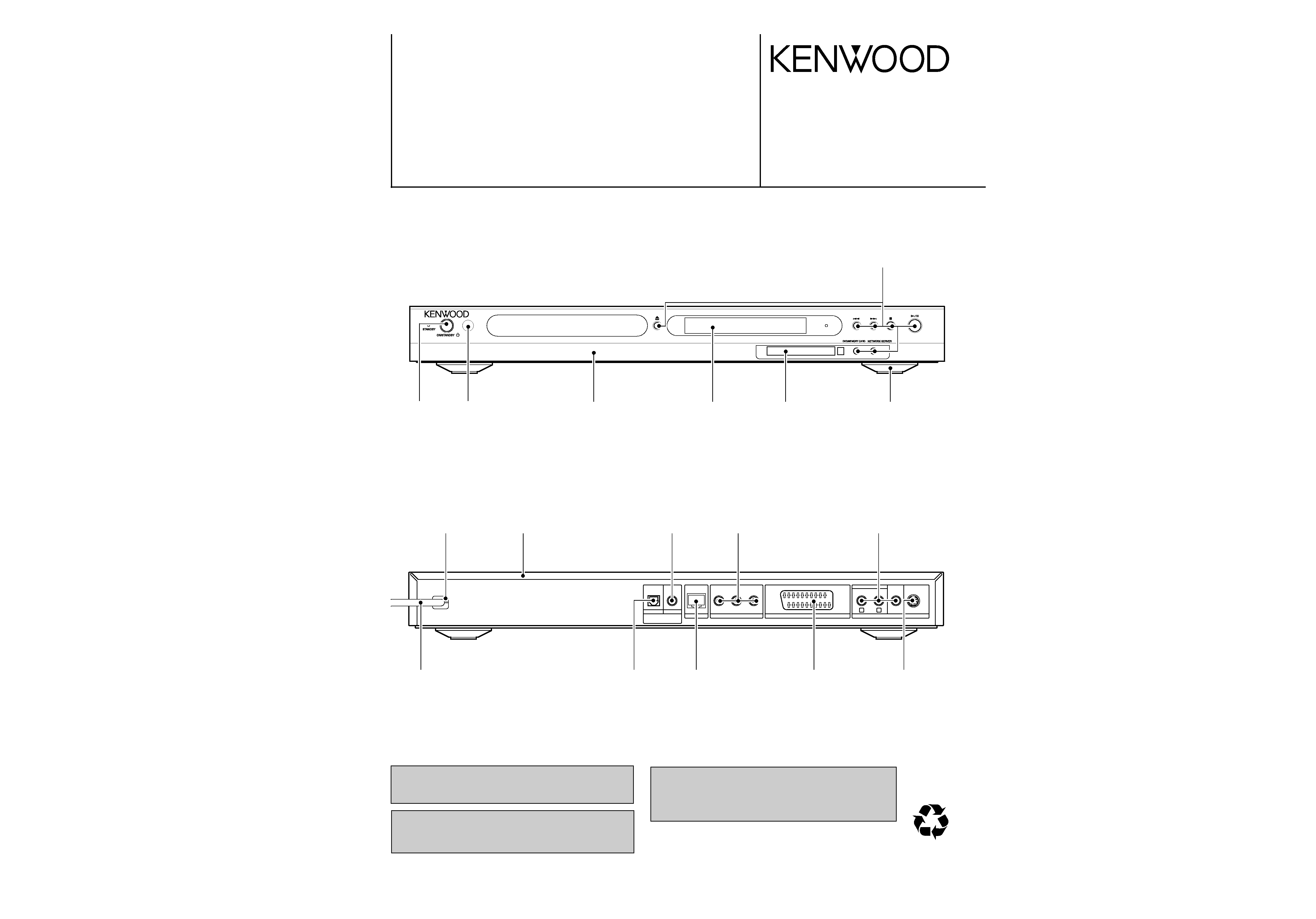
Location: Back panel
CAUTION
VISIBLE LASER RADIATION
WHEN OPEN. DO NOT
STARE INTO BEAM.
Inside this laser product, a laser diode classified as
Class 2 laser radiation is contained as alerted by the
internal caution label shown above. Do not stare
into beam.
Location: DVD laser pick-up unit cover inside this
product
Caution on condensation
Before transporting or moving this unit, carry out the
following operations.
1. Set the ON/STANDBY switch to ON without
loading a disc.
2. Set the input selector to DVD.
3. Wait a few seconds and verify that the display
below appears.
"NO DISC"
4. Set the ON/STANDBY switch to OFF.
5. Remove the PC card adapter.
Note related to transportation and movement
Condensation (of dew) may occur inside the unit when there is a big
difference in temperature between this unit and the outside. This unit
may not function properly if condensation occurs. In this case, leave
the unit for a few hours and restart the operation after the condensa-
tion has dried up.
Be specially cautious against condensation in the following circum-
stances:
When this unit is carried from one place to another across a big
difference in temperature, when the humidity in the room where
this unit is installed increases, etc.
Resetting
Erroneous operation (operation impossible, wrong display indication, etc.) may occur when a connection cable
is connected or disconnected while the power is on or because of an external influence. In such a case, try the
following procedure.
Soft reset
Press the ON/STANDBY key to switch to standby status. Wait for approx. 10 seconds and then press the ON/
STANDBY key again to switch on the power.
÷ When a memory card has been inserted, press the ON/STANDBY key, remove the card after standby status
has been reached, and then press the ON/STANDBY key again to switch on the power.
÷ The contents of the settings registered by you remain as they are.
Return to the factory shipping status
Bring the unit to STANDBY status and press the ON/STANDBY key while keeping the
7 (STOP) key pressed.
÷ Please note that the contents of the settings registered by you will be deleted.
CLASS 1
LASER PRODUCT
Trademark Information
÷ Manufactured under license from Dolby Laboratories.
"Dolby", "Pro Logic" and the double-D symbol are trade-
marks of Dolby Laboratories.
÷ "DTS" and "DTS Digital Out" are regis-
tered trademarks of Digital Theater
Systems, Inc.
÷ Microsoft and Windows are registered
trademarks or trademarks in the USA
and other countries of Microsoft Corporation.
÷ IBM and PC/AT are registered trademarks of International
Business Machines Corporation.
÷ Pentium is a trademark or registered trademark of Intel
Corporation.
÷ Java and all trademarks and logo marks related to Java are
registered trademarks or trademarks in the USA and other
countries of Sun Microsystems Inc.
÷ Memory Stick is a trademark of Sony Corporation.
÷ DivX, DivX Certified, and associated logos are trademarks
of DivXNetworks, Inc. and are used under license.
Other system names and product names are also trademarks
or registered trademarks of their respective developers. Note
that the "TM" and "®" markings are omitted in the text of this
manual.
background image
DVF-N7080/N7080-S
4
DISASSEMBLY FOR REPAIR
How to open the tray if it does not come out.
1. Insert a flat driver and pull it down in the drawing through
the hole on the loading chassis bottom.
2. Pull out the tray frontward by hand when it comes just out.
background image
2
ACE
G
I
BD
F
H
J
1
3
5
7
4
6
R311
R336
R335
R116
L17
L13
L27
L26
C16
C19
R321
1
7
14
C127
8
R326
C94
C13
C93
R328
R327
R14
C18
R320
R325
R109
R324
R2
C12
C51
R19
R11
C17
R18
R12
C21
5
8
R55
W8
C95
4
1
R6
R7
R110
R111
C97
1
13
2
C98
C15
R1
C96
R54
W7
86
C75
C80
R308
R306
R307
R4
CP3
CP4
C53
R201
1
CP9
R120
CP10
CP2
CP1
R323
R322
L205
L204
L208
L203
L202
L201
L207
L10
R313
R302
C77
C76
44
R74
C70
R61
43
R314
R301
C213
R343 L212
R304
R303
C207
C206
L206
R13
R53
C82
C63
C87
W4
C31
R93
C90
C88
39
62
1
1
3
1
3
5
40
C50
R205
C64
C203
CP11
CP12
R125
R203
R202
R121
R204
R126
CP8
R207
R206
R123
CP13
R124
C57
1
R331
C61
R341
R332
R330
W18
R329
R312
C202
8
W19
D
ATA
CLOCK
C210
L210
1
VCC
R310
L209
C209
C79
5
R309
C205
R81
R84
27
C58
R83
4
2
1
W17
R82
W14
R86
54
1
C55
R79
C71
C52
C81
C54
R94
C83
C91
L213
C84
54
127
A
AG
C78
C62
C56
C48
1
28
1
24
27
24
28
W16
48
48
25
R85
9
8
C72
W15
25
59
60
R137
R117
C101
C102
W11
L9
L11
L8
L44
W10
L43
C5
L42 C99
L41
R42
R338
R51
B
8
1
R131
R8
R339
9
16
R36
E
R130
R9
R33
R337
R38 R52
W6
C29
R43
L211
C86
W5
L12
R41
C30
L18
L14
R112
BE
R34
R32
BE
R340
BE
C39
R35
R37
R40
C126
R39
BE
BE
C65
C211
R44
C32
7
5
BE
BE
R114
R49
R3
R115
1
8
7
T1
C44
L7
L6
L5
L48
C73
C40
R63
W3
R342
W12
R64
51
R46
50
R56
C43
R57
4
C74
75
R45
76
1
1
10
C204
1
10
R142
C68
C46
C45
C41
R59
R58
R60
25
26
C42
L45
L47
L46
L15
L16
R334
L24
R143
1
100
1
X1
R141
R140
R139
R138
C92
L4
C59
R62
C49
X2
C60
8
14
8
7
1
7
8
R128
R127
14
8
1
14
7
8
C67
1
16
C212
C69
14
9
1
14
8
11
16
20
1
11
C134
R48
C133
R98
20
R101
R99
R100
7
R97
8
C66
R66
R129
R68
W1
R305
C100
1
C6
C135
8
R65
C201
C208
4
5
16
W9
W2
16
1
9
C9
9
8
1
8
R136
1
14
81
7
1
2
1
1
5
1
6
1
7
8
14
1
74
1
6
1
6
1
9
2
8
26
17
OI
G
CN7
CN23
CN3
CN16
CN15
D10
CN11
CN18
D13
CN13
CN12
CN14
CN2
CN17
Q9
D9
Q13
D3
D2
D1
Q10
Q7
Q8
Q11
Q6
Q12
D4
D11
CN5
CN4
D12
CN1
CN8
CN6
D7
IC38
IC9
IC21
IC18
IC42
IC202
IC200
IC43
IC22
IC20
IC17
IC52
IC12
IC48
IC46
IC14
IC47
IC203
IC54
IC49
IC50
IC53
IC10
IC55
IC201
IC57
X17-1102-70 (J75-0013-12) (SIDE A)
Refer to the schematic diagram for the value of resistors and capacitors.
PC BOARD
5
6

Reviews

There are no reviews of this manual yet.