Audio
(E30-0505-05)
(E30-2725-05)
(E30-1427-05)
(B19-1529-05)
(E03-0115-05)
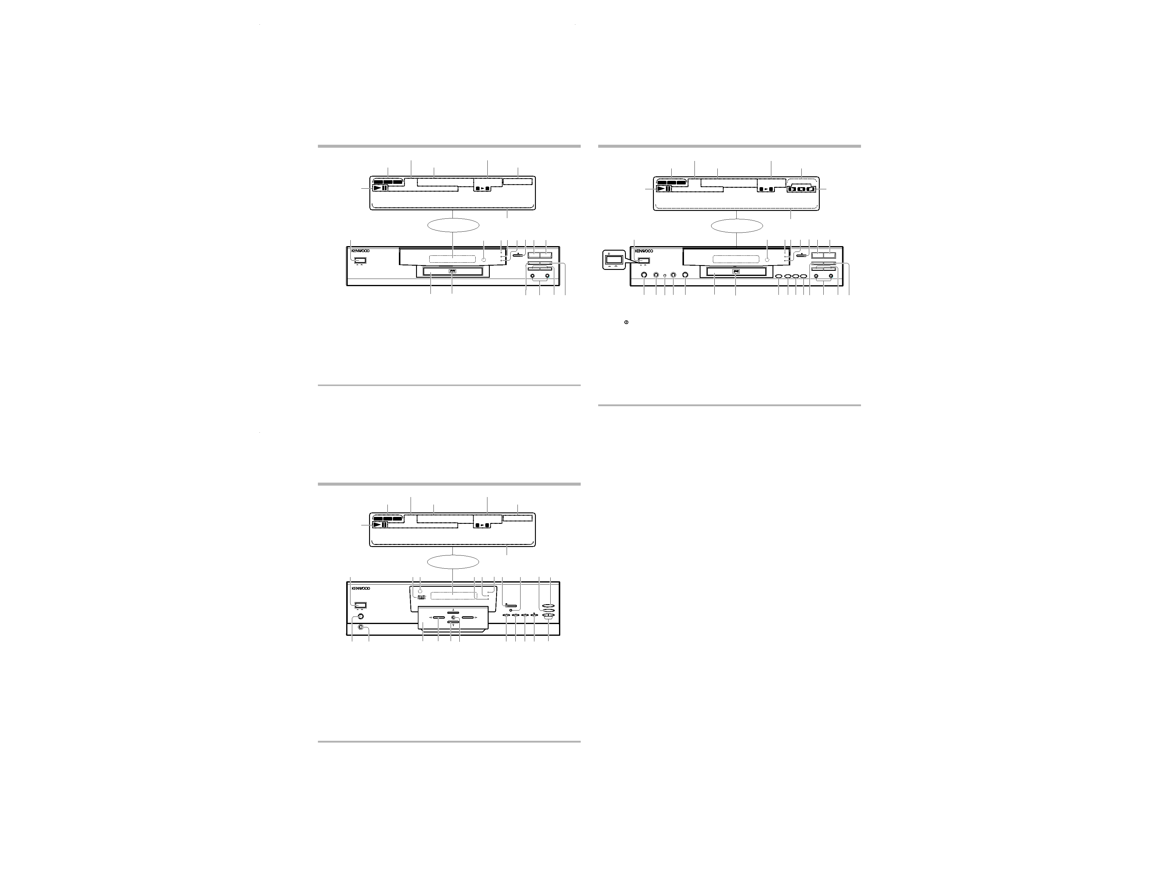
(A70-1229-05) : DVF-K7010
(A70-1230-05) : DV-203/DVF-5010
(A70-1227-05) :
DV-2070/DVF-9010
Battery cover (A09-1105-05)
Battery cover
(A09-1124-08)
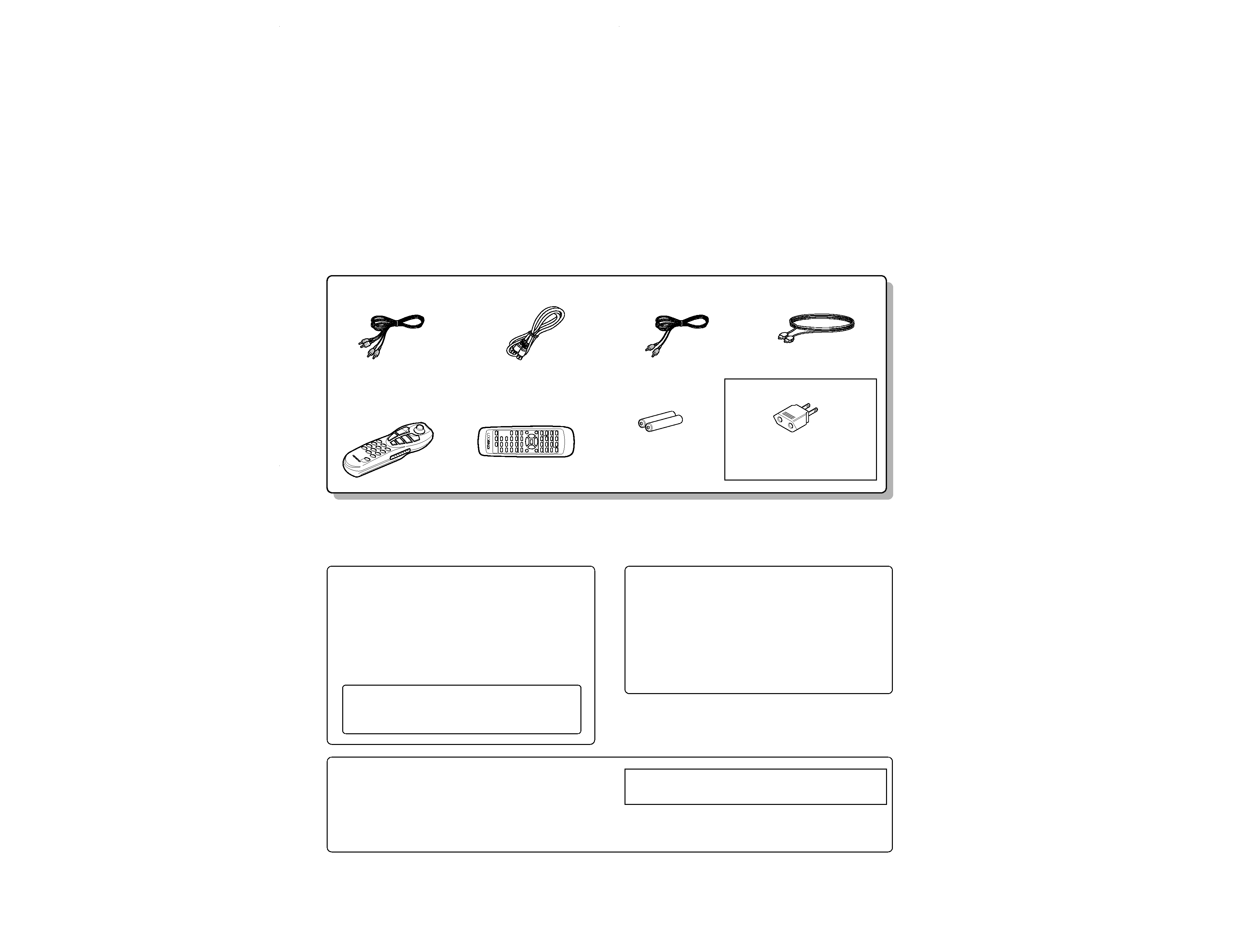
cord (Red, White) ...... (3)
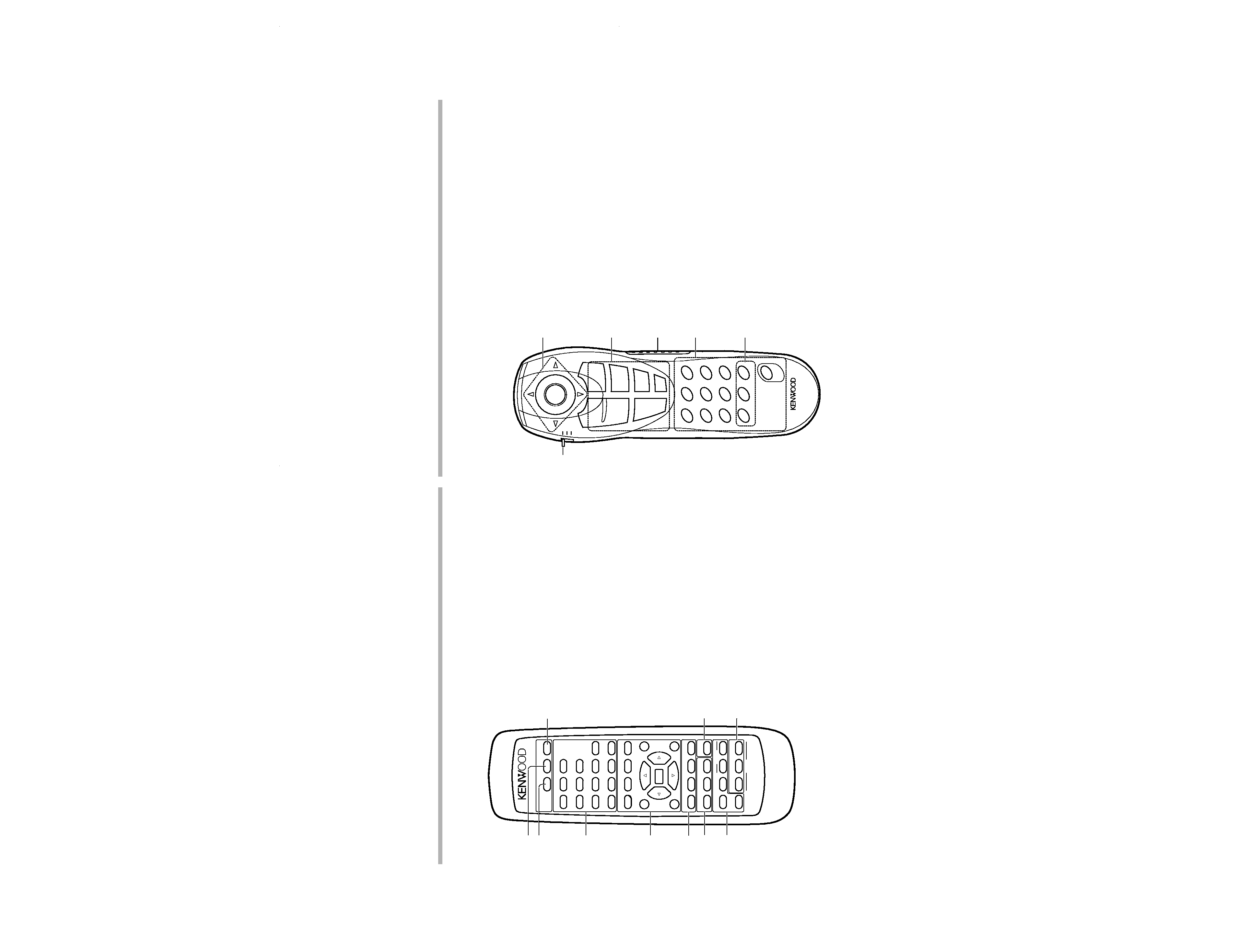
Remote control unit ............. (1)
Batteries (R6/AA) ........ (2)
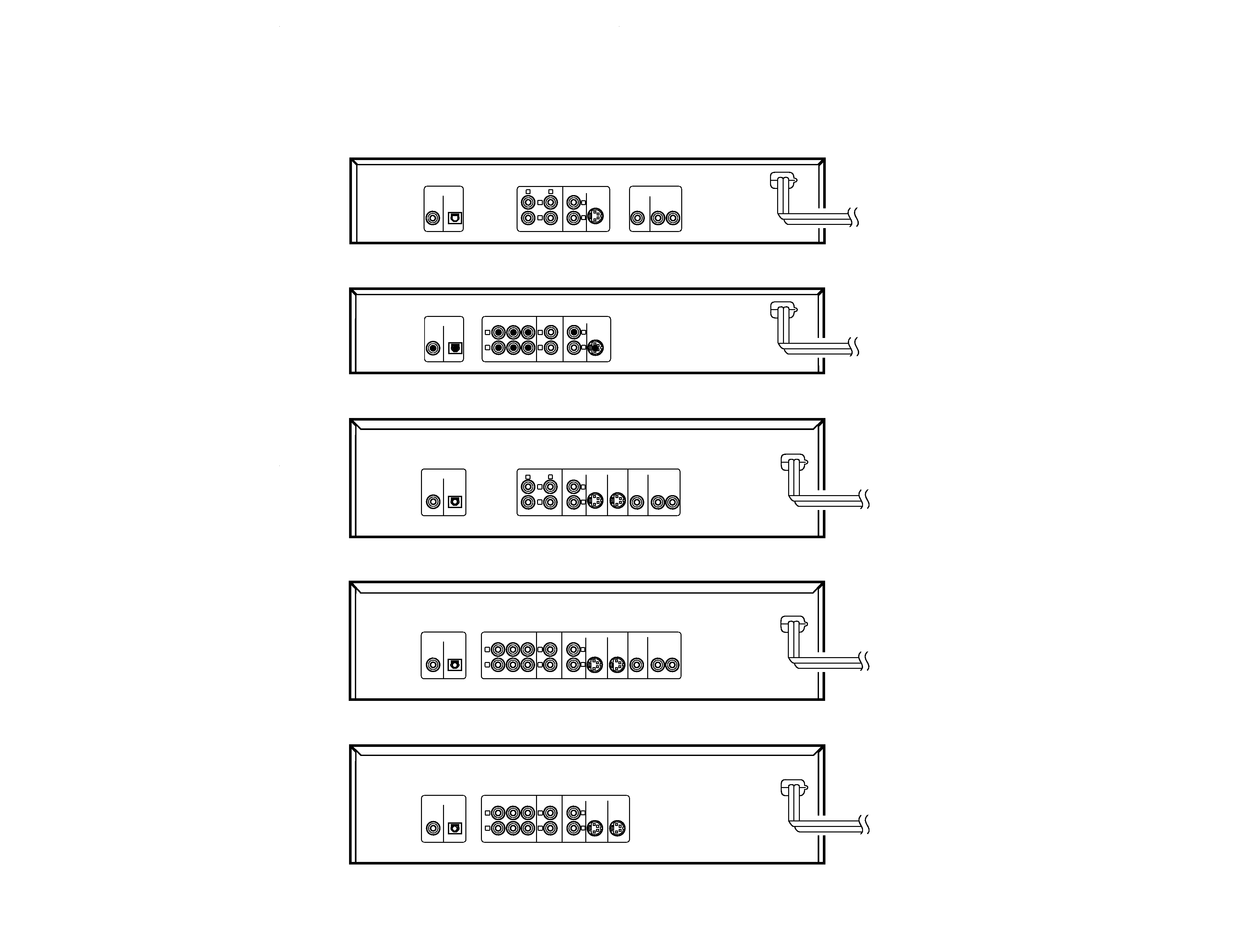
Optical fiber cable ............. (1)
S-VIDEO cord ...................... (1)
Video cord (Yellow) ............. (1)
AC plug adaptor ............. (1)
Use to adapt the plug on the power cord
to the shape of the wall outlet.
(Accessory only for regions where
use is necessary.)
Remote control unit ............. (1)
DVD VCD CD
P.B.C.
DOLBY DIGITAL
RANDOM PROG.
STEREO
ANGLE
REPEAT ALL
KARAOKE
LR
TITLE CHAPTER TRACK CD TEXT
A
B
N O DISC
Beware of condensation
When the difference between the internal temperature of the unit and
external atmosphere is large, dew (mist) may be produced on the
internal parts of the unit. In such a case, turn the unit ON and leave
it for a few hours until the condensation has dried up.
Be especially careful in the following conditions:
When the unit is brought into a place where there is a large difference
in temperature between the previous location, when the humidity of
the listening room is high, etc.
Note related to transportation and
movement
Before transporting or moving this unit, carry out the following
operations.
1. Set the POWER key to ON without loading a disc.
2. Wait a few seconds and verify that the display shown appears.
3. Set the POWER key to OFF.
Operationtoreset
The microprocessor may fall into malfunction (impossibility to operate
erroneous display, etc.) when the power cord is unplugged while power
is ON or due to an external factor. In this case, execute the following
procedure to reset the microprocessor and return it to normal condi-
tion.
÷ Please note that resetting the microprocessor clears the contents
stored in, it returns the microprocessor to the condition when it left
the factory.
While holding the
7 key, press and hold the 8 key until "INITIAL OK!"
appears.
DV-203/2070/DVF-5010/9010/K7010
2
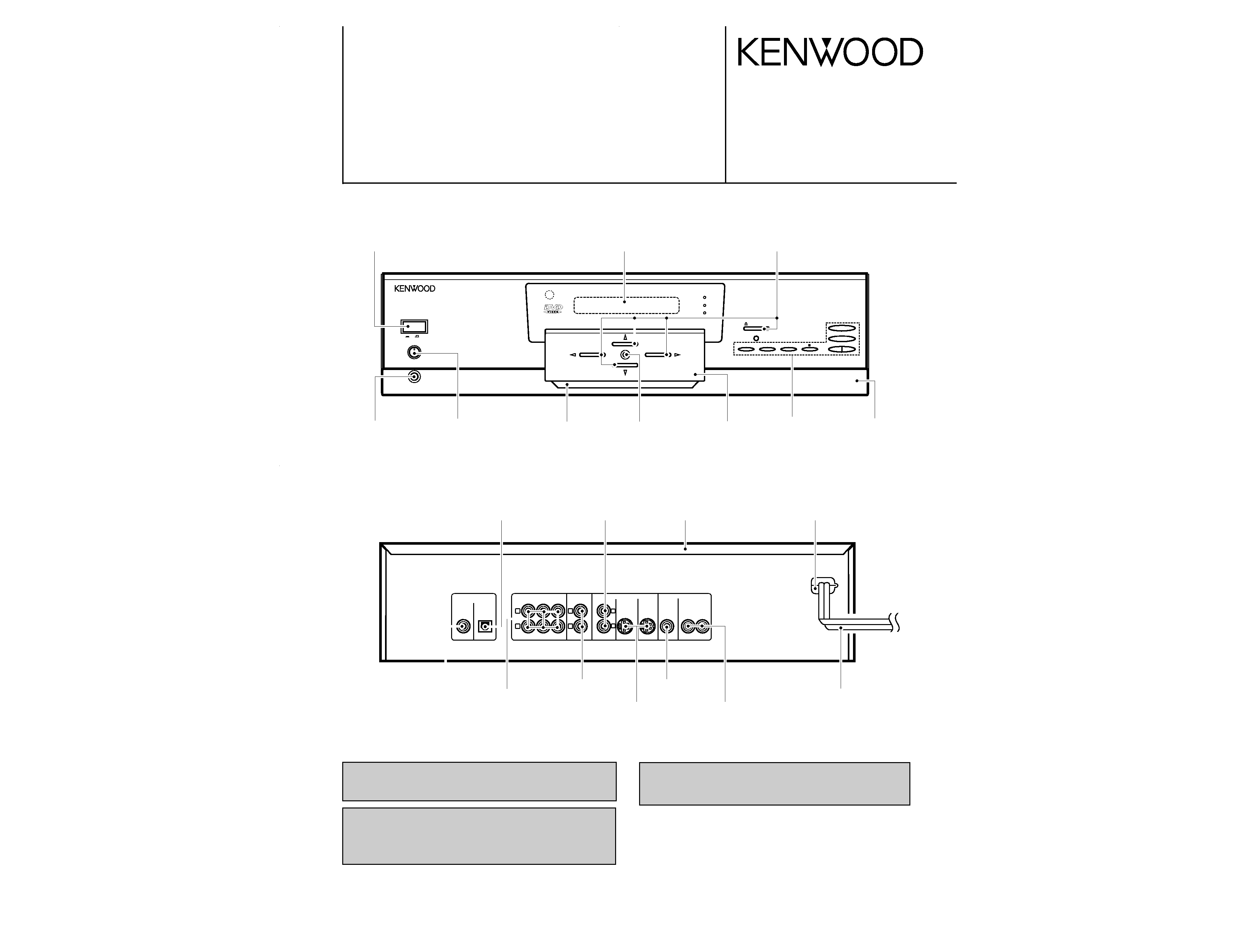
CONTENTS / ACCESSORIES
CONTENTS / ACCESSORIES ....................................2
CONTROLS .................................................................3
DISASSEMBLY FOR REPAIR .....................................6
BLOCK DIAGRAM .....................................................11
CIRCUIT DESCRIPTION ...........................................13
ADJUSTMENT .......................................................... 24
WIRING DIAGRAM ....................................................26
PARTS DESCRIPTIONS ...........................................27
PC BOARD ................................................................28
SCHEMATIC DIAGRAM ............................................33
EXPLODED VIEW .....................................................49
PARTS LIST...............................................................52
SPECIFICATIONS .....................................................67
Contents
Accessories
Cautions
DV-203/DVF-5010(K)COVER1,1(98.12.1114:21 y[W 3