KENWOOD DPX-MP7050 Service Manual

Cover page of KENWOOD DPX-MP7050 Service Manual

Service Manual for KENWOOD DPX-MP7050, downloadable as a PDF file.

We also have owner's manual to this model.

Manual details

  • Immediate download after payment.
  • Delivered as a PDF file.
  • The manual has 44 pages
  • File size: 2.11 MB
  • Available language versions: English
  • Different language versions may vary sligthly in file size and page count.

We guarantee that...

  • our manuals are complete,
  • the manual includes circuit diagrams,
  • our manuals are checked with antivirus,
  • We'll issue refund if the manual is damaged, incomplete or unreadable (our refund policy)

Sample pages

Thumbnail of page 1Thumbnail of page 2Thumbnail of page 3Thumbnail of page 4
Thumbnail of page 5Thumbnail of page 6Thumbnail of page 7Thumbnail of page 8
Thumbnail of page 9
background image
© 2003-10 PRINTED IN JAPAN
B53-0095-00 (N) 449
CD CASSETTE DSP RECEIVER
DPX-MP7050
SERVICE MANUAL
Size AA battery
DOLBY B NR
Panel (FRONT)
(A64-3340-08)
DC cord assy
(E30-6332-08)
Escutcheon assy
(B07-3046-04)
Remote controller assy(RC-515)
(A70-2042-05)
Screw set
(N99-1724-05)
background image
© 2003-10 PRINTED IN JAPAN
B53-0095-00 (N) 449
CD CASSETTE DSP RECEIVER
DPX-MP7050
SERVICE MANUAL
Size AA battery
DOLBY B NR
Panel (FRONT)
(A64-3340-08)
DC cord assy
(E30-6332-08)
Escutcheon assy
(B07-3046-04)
Remote controller assy(RC-515)
(A70-2042-05)
Screw set
(N99-1724-05)
background image
DPX-MP7050
2
BLOCK
DIA
GRAM
TAPE
AM
CD
MUX
CD
FRONT
REAR
FRONT
REAR
5L-BUS
12C-BUS
I2C-BUS
TUNER
SW IC
IC271
IC4
SW IC
TAPE (TN70B)
CD
CD-CH
AUX IN
MPX/NC
FADER
SW
(VOL)/
TONE
FADER
E VOL/MPX
IC2
SEL/VOL/LPF
IC5
SYSTEM E'S
HPF
MUTE
IC12
POWER IC
FRONT
REAR/
DSP
IC8
BUFF
IC9-11
E2P-ROM
IC901
PANEL u-COM
IC1
MAIN u-COM
LEVEL
IC903
REMOTE
SENSOR
MATRIX
KEY
VFD
DRIVER
MOTOR
IC270
DRIVER
MOTOR
IC14
PANEL
MECHA
(DD-CONV)
SI-B033JD
DSP 3.3V
CD MECHA
DC/DC 11V
ILL 11V
TAPE 16V
CD SERVO 7.5V
SW 16V
DSP 3.3V
BU 5V
A 8V
REG IC
IC105
(MP3,WMA)
E2P-ROM
(EQ/DB)
TU1
EQ IC
IC250
(L/R/GND)
N-F
DRV
MUTE
DRV
SHIFT
Q201,301
Q202,302
IC904
background image
DPX-MP7050
3
MAIN UNIT
Ref. No.
Application/Function
Operation/Condition
IC1
MAIN
µ-COM
IC2
Electronic Vol/MPX
Electronic Vol/MPX
IC4
SW IC
CD/TAPE
IC5
SYSTEM E'S
SYSTEM E'S
IC7
Buff
IC8
DSP
DSP
IC9~11
Buff
IC12
POWER IC
IC14
MOTOR DRIVER
IC15
RST
IC16
MUTE
IC17
REG IC
IC105
REG IC
IC150
REG IC
MP3/WMA
IC250
EQ IC
EQ/B NR
IC270
MOTOR DRIVER
IC271
SW IC
AUX/CD-CH
Q1
BU_DET SW
Q2
ACC, BU_DET SW
Q3
ILL SW
Q5
ANP_CONT SW
Q6,7
P-ANT SW
Q8
P-CON SW
Q9
P-ON SW
Q10
SURVO7.5V SW
Q11~13
SURVO7.5V AVR
7.5V power supply for CD mechanism
Q16
MOTOR DRIVER SW
Q17,18
MOTOR DRIVER AVR
Power supply for motor driver
Q19
ILL 11V SW
Q20,21
ILL 11V AVR
Power supply for ILL
Q22
DD-CONV SW
Q23,24
DD-CONV AVR
Power supply for DC/DC converter
Q26
LED OPEN SW
Q30
BU_DET SW
Q52
AM+B SW
Q53
FM+B SW
Q54
TUNER_CONT SW
Q101,102
RST SW
Q150,151
MAIN MOTOR AVR
Power supply for the main motor driver of cassette mechanism
COMPONENTS DESCRIPTION
background image
DPX-MP7050
4
CONTROL UNIT
Ref. No.
Application/Function
Operation/Condition
IC901
PANEL
µ-COM
IC902
REG IC
IC903
LEVEL SIFT
IC904
REMO
Remote controller light reception
Q901
DISPLAY_BLANKING SW
Q902
VFD AVR
Q903
DD-CONV SW
Q904
LED SW
LED SW for DSI
Q905
RST SW
Q906,907
REMO SW
COMPONENTS DESCRIPTION
Ref. No.
Application/Function
Operation/Condition
Q152
MP3/WMA SW
Q153,154
MOTOR DRIVER AVR
Power supply for the sub motor driver of cassette mechanism
Q201,202
MUTE DRV
Mute SW for PRE-OUT
Q301,302
MUTE DRV
Mute SW for PRE-OUT
Q401
INPUT_SEL SW
Q403,404
MUTE SW
Q406,407
MUTE SW
Q801
MOTOR DRIVER SW
Q805
INPUT_SEL SW
background image
DPX-MP7050
5
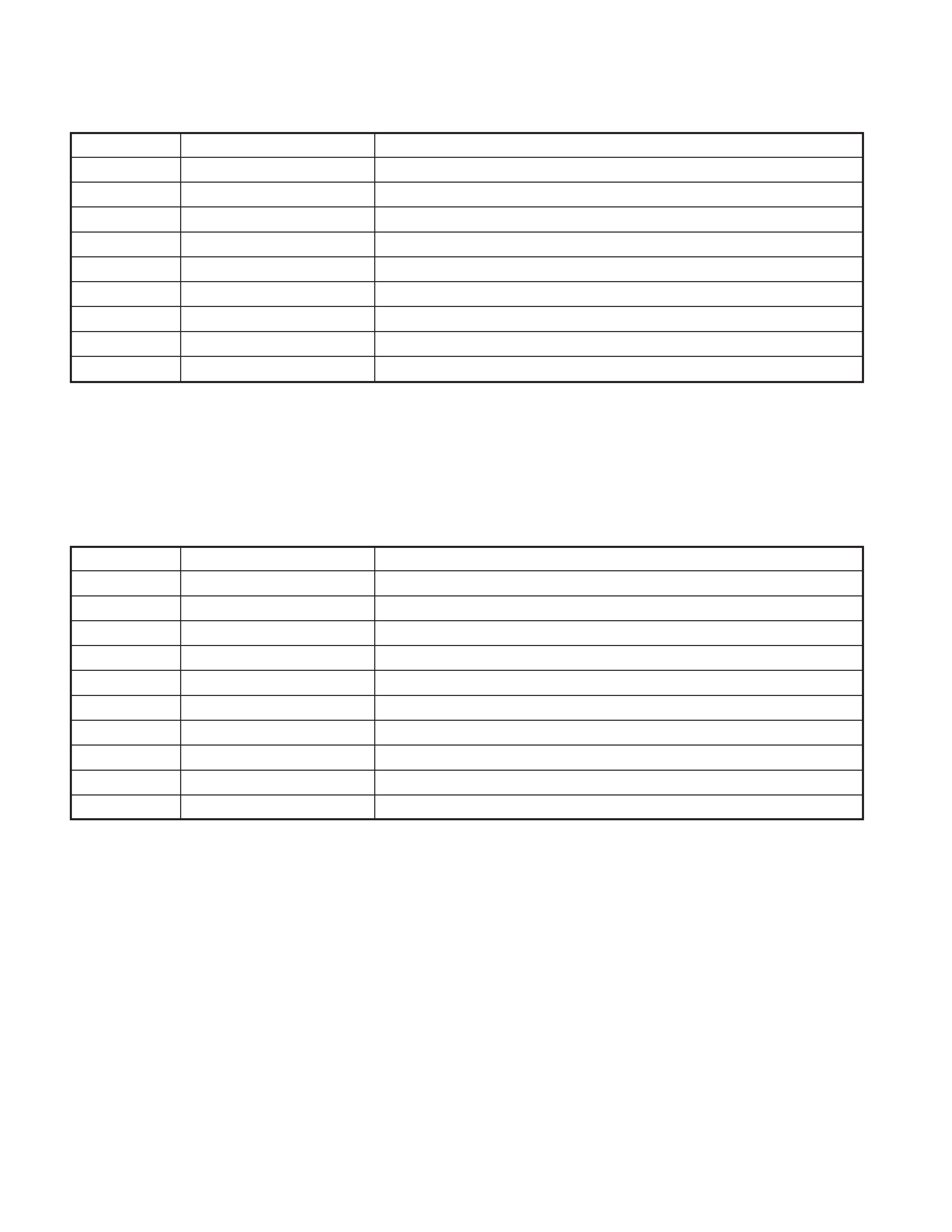
MICROCOMPUTER'S TERMINAL DESCRIPTION
Pin No.
Pin Name
I/O
Application
Truth Value
Processing Operation Description
Table
1
DSP_RVDT
O
DSP data output
2
DSP_CLK
O
DSP clock output
3
DSP_RST
O
DSP Reset
L : Reset
4
DSP_XLAT
O
DSP address/data switching
5
LX_DATA_M
O
Data to Slave unit
6
LX_DATA_S
I
Data from Slave unit
7
LX_CLK
I/O
LX BUS clock
8
BYTE
-
9
CNVSS
-
10
LX_CON
O
Start request for Slave unit
H : Slave unit ON, L : Slave unit OFF
11
LX_REQ_M
O
Communication request for Slave unit
12
RESET
-
13
XOUT
-
14
VSS
-
15
XIN
-
16
VCC
-
17
NMI
I
18
PN_REQ
I
Control on between-panel communication
19
SP_INT
I
Spectrum analyzer request
20
LX_REQ_S
I
Communication request from Slave unit
21
BUDET
I
Momentary power dropped detection
H : Normal, L : Momentary power dropped
22
ACCDET
I
ACC power supply detection
H : ACC OFF
23
ILLUMI
I
Dimmer ILL detection
24
AMP_CTRL
O
External amp detection
25
PWIC_TEST
O
Power IC test mode control
High during momentary power dropped
26
BUZZ
O
Beep output
27
PWIC_SVR
O
28
PWIC_STBY
O
Power IC standby control
29
SCL
I/O
I2C Bus
30
SDA
I/O
I2C Bus
31
SYS_DATA
O
Between-panel communication output
32
PN_DATA
I
Between-panel communication input
33
PN_CLK
O
Between-panel communication clock
34
SYS_REQ
O
Between-panel communication control (FLASH BUSY)
35
TUN_TYPE0
I
Destination setting 1
t
36
TUN_TYPE1
I
Destination setting 2
t
37
P_ANT
O
Power ANT Control terminal
H : ANT ON
(note) P_CON must be hi.
L : ANT OFF
38
P_CON_IN
I
External amp excess current control
39
P_CON
O
External amp current control
H : ON
40
PON
O
Power supply control
H : ON
41
LAMP
O
Key ILL control (FLASH EPM)
42
DISC_LED
O
Disc insert gate ILL
43
SI
O
LED control for SI
44
NC
O
45
SP_REQ
O
Spectrum analyzer enable output
46
PN_SCCON
O
Between-panel communication control (FLASH CE)
47
ROMCOL_WR
I
Setting for ROMCOL E2P exist or not
H : Write to E2P
SYSTEM MICROCOMPUTER : M30624MGAB15FP (MAIN UNIT : IC1)

Reviews

There are no reviews of this manual yet.