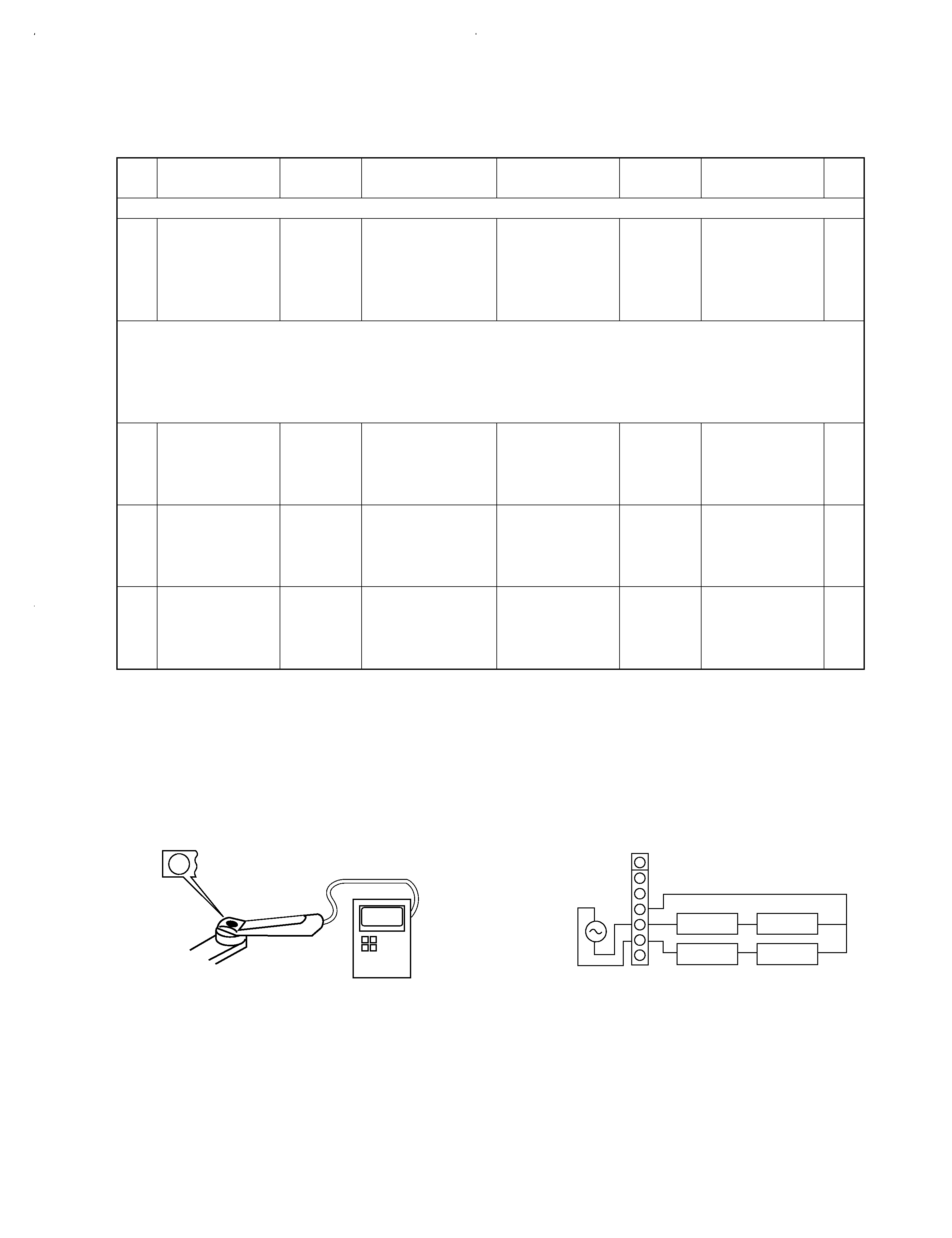
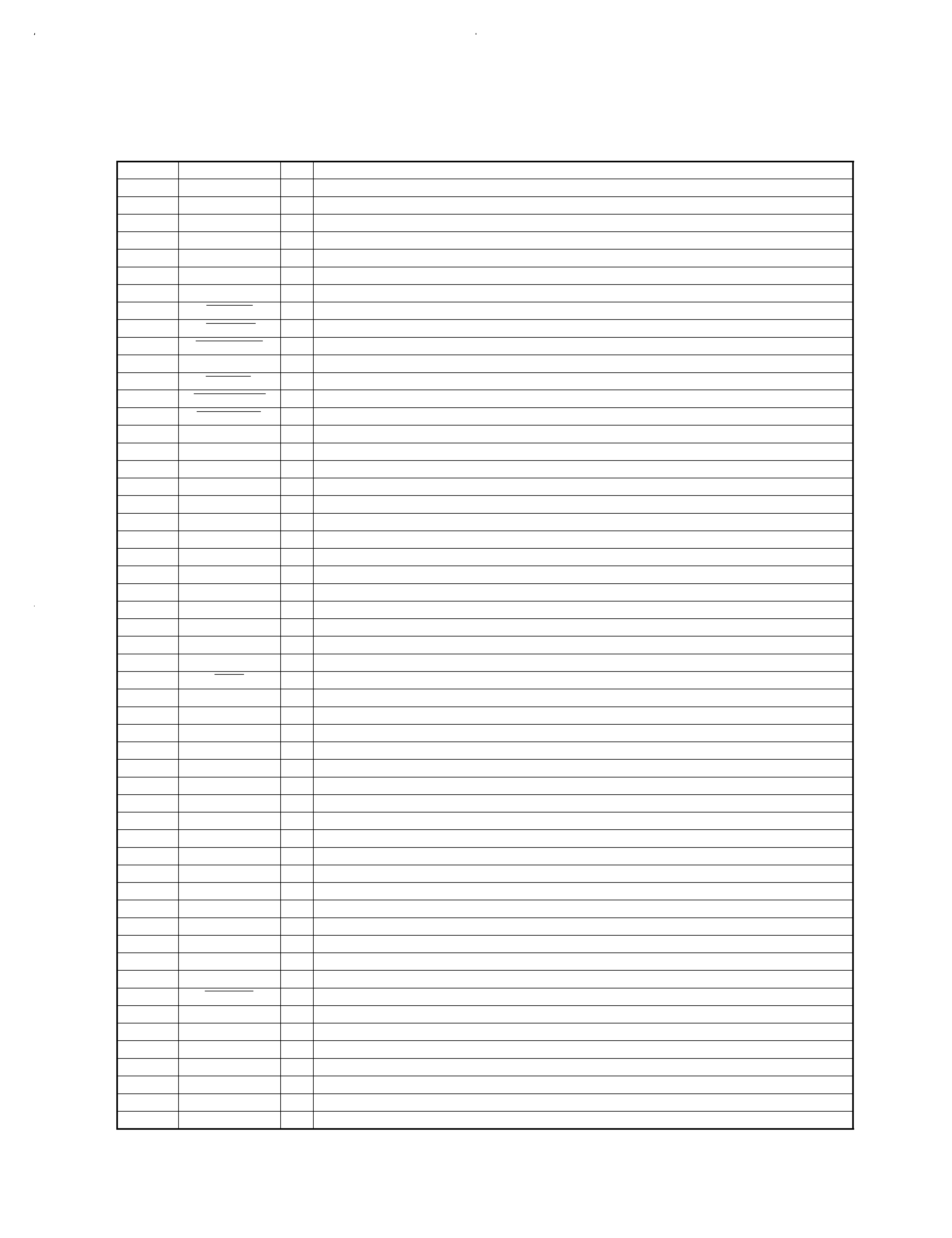
KENWOOD DOFR3010E Service Manual

Cover page of KENWOOD DOFR3010E Service Manual

Service Manual for KENWOOD DOFR3010E, downloadable as a PDF file.

Manual details

  • Immediate download after payment.
  • Delivered as a PDF file.
  • The manual has 17 pages
  • File size: 1.83 MB
  • Available language versions: English
  • Different language versions may vary sligthly in file size and page count.

We guarantee that...

  • our manuals are complete,
  • the manual includes circuit diagrams,
  • our manuals are checked with antivirus,
  • We'll issue refund if the manual is damaged, incomplete or unreadable (our refund policy)

Sample pages

Thumbnail of page 1Thumbnail of page 2Thumbnail of page 3Thumbnail of page 4
Thumbnail of page 5Thumbnail of page 6Thumbnail of page 7Thumbnail of page 8
Thumbnail of page 9
background image
MULTIPLE CD PLAYER
CD-203/DPF-R3010/DPF-R3010E
CD-204/DPF-R4010/DPF-R4010E
SERVICE MANUAL
© 1998-3/B51-5417-00 (K/K) 3430
CHECK
CLEAR
TIME DISP.
REPEAT
RANDOM
P.MODE
DISC SKIP
EDIT
4
¢
1
¡
DISC 1
DISC 2
DISC 3
DISC 4
DISC 5
0
6
7
PHONES
-ON ­STANDBY
L
R
SL16 XS 8
SYSTEM
CONTROL
LINE OUTPUT
Panel*
(A60-)
Knob *
(K27-)
AC power cord *
(E30-)
Slide switch
(S31-2132-05)
Phono jack
(E63-0122-05)
Miniature phone jack
(E11-0293-05)
Power cord bushing
(J42-0083-05)
Front glass
(B10-2441-03)
KENWOOD badge
(B43-0302-04)
Knob *
(K29-)
Phone jack
(E11-0272-05)
Panel (TRAY) *
(A29-)
Illust is CD-204/DPF-R4010/DPF-R4010E.
* Refer to parts list on page 16.
In compliance with Federal Regulations, following are reproduc-
tions of labels on, or inside the product relating to laser product
safety.
KENWOOD-Crop. certifies this equipment conforms to DHHS
Regulations No. 21 DFR 1040. 10, Chapter 1, Subchapter J.
DANGER : Laser radiation when open and interlock defeated.
AVOID DIRECT EXPOSURE TO BEAM
Refer to 103CD/104CD/1050CD, DP-R797/R3090/R4090
(B51-5269-00) if you require circuit description and block
diagram in detail.
CD-203/DPF-R3010(K)COVER( 98.4.2411:30PM y[W 2
background image
CD-203/204/DPF-R3010/R3010E/R4010/R4010E
2
CONTENTS / ACCESSORIES
CONTENTS / ACCESSORIES .................................. 2
CIRCUIT DESCRIPTION ........................................... 3
ADJUSTMENT ........................................................... 5
PC BOARD ................................................................ 6
SCHEMATIC DIAGRAM ............................................ 9
EXPLODED VIEW ................................................... 14
PARTS LIST............................................................. 16
SPECIFICATIONS ..................................... Back cover
Contents
Accessories
Audio cord (1)
(E30-0505-05)
System control cord (1)
(E30-2816-05)
AC plug adapter (1)
(E03-0115-05)
DPF-R3010/R4010 : M type only
Remote control unit (1)
(A70-1128-05) : RC-P0504
CD-204/DPF-R4010/DPF-R4010E only
Batteries (R6/AA) (2)
CD-204/DPF-R4010/DPF-R4010E only
Battery cover: (A09-0356-08)
HOW TO READ THE PARTS LIST
ABBREVIATION OF MODEL AND MASS PRODUCTION'S DESTINATIONS
MODEL
ABB.
Australia
Canada
China
England
Europe
Germany
Korea
Malaysia
CD-203
-
-
P3
-
-
-
-
-
-
DPF-R3010
-
X3
-
-
T3
E3
-
-
-
DPF-R3010E
-
-
-
-
-
E4
-
-
-
CD-204
-
-
P1
-
-
-
-
-
-
DPF-R4010
-
X1
-
-
T1
E1
-
-
-
DPF-R4010E
-
-
-
-
-
E2
-
-
-
MODEL
ABB.
Mexico
PX/AAFES
Russia
Scandinavia
Shanghai
USA
Other area
CD-203
-
-
-
-
-
-
K3
-
-
DPF-R3010
-
-
Y3
-
-
-
-
M3
-
DPF-R3010E
-
-
-
-
-
-
-
-
-
CD-204
-
-
-
-
-
-
K1
-
-
DPF-R4010
-
-
Y1
-
-
-
-
M1
-
DPF-R4010E
-
-
-
-
-
-
-
-
-
CD-203/DPF-R3010(K)COVER( 98.4.2411:30PM y[W 3
background image
1. Pin description
Pin No.
Name
I/O
Function
1~7
7G~1G
O
Display digit control (Grid7~Grid1)
8
VDD
Power supply (+5V)
9
SQCK
O
Q data reading clock output
10
NC
O
Unused
11
SUBQ
I
Q data input
12~15
KR3~KR0
I
Key return 3~0
16
NC
I
Unused
17
RESET
I
Reset input
L : RESET
18
SLT SW
I
CDM25 start limit switch input
L : SW ON
19
DOWN SW
I
CDM25 mechanism down switch input
L : SW ON
20
AVSS
I
Unused (connected to VSS)
21
UP SW
I
CDM25 mechanism up switch input
L : SW ON
22
CLOSE SW
I
CDM25 close switch input
L : SW ON
23
OPEN SW
I
CDM25 open switch input
L : SW ON
24
OPEN M
O
Open motor control
H : ACTIVE
25
CLOSE M
O
Close motor control
H : ACTIVE
26
RTRAY R
O
Rotary tray motor control (CW)
H : ACTIVE
27
RTRAY L
O
Rotary tray motor control (CCW)
H : ACTIVE
28
RTRAY S
O
Rotary tray motor control (deceleration)
H : ACTIVE
29
AVDD
Unused (connected to VDD)
30
AVREF
Unused (connected to VSS)
31
NC
I
Unused
32
XT2
Unused (OPEN)
33
VSS
GND
34
X1
I
System clock input
35
X2
Unused
36
DSENSE
I
CDM25 disc sensor detection
37
PSENSE
I
CDM25 position sensor detection
38
LDC
O
Laser signal output
L : LASER ON
39
FOK
I
FOK signal input
H : FOCUS ON
40
D.R.I.V.E
I
Unused
42
SDATA
I/O
System serial data signal input output
43
BUSY
I/O
System serial busy signal input output
44
SCOR
I
Sub code frame sync detection
45
MON
O
Focus drug countermeasure circuit control
46
MUTG
O
Digital mute control
H : MUTE ON
47
REM
I
Remote control signal input
48
VPP
GND
49
SENSE
I
Sense input from CXD2507AQ
50
DTA
O
Data output for CXD2507AQ
51
CLK
O
Clock output for CXD2507AQ
52
VDD
Power supply (+5V)
53,54
DEFECT SEL./NC
I
Unused
55
LAT
O
Latch output for CXD2507AQ
56
GFS
I
Frame signal input
57
RMUTE
O
Analog mute control
L : MUTE ON
58
MDT
O
Attenuater data output
59
MCK
O
Attenuater clock output
60
MEL
O
Attenuater latch output
61~70
Sp~Sg/KS
O
Display segment control (Seg p-Seg g) / Key scan
71
VLOAD
Display drive negative power supply (-35V)
72~77
Sf~Sa/KS
O
Display segment control (Seg f-Seg a) / Key scan
78~80
10G-8G
O
Display digit control (Grid10-Grid8)
41
SERIAL SW
I
Serial communication 8 (XS8)/16(SL16) bit changover
H : 16 BIT
CD-203/204/DPF-R3010/R3010E/R4010/R4010E
3
CIRCUIT DESCRIPTION
CD-203/DPF-R3010(K)COVER( 98.4.2411:30PM y[W 6
background image
CD-203/204/DPF-R3010/R3010E/R4010/R4010E
4
CIRCUIT DESCRIPTION
Step
Key name
Display
Description
1
PLAY/PAUSE
(Cyclic)
03
(1) Focus servo ..........................................................................ON
TE-B adjustment
(2) Tracking servo ......................................................................OFF
(3) Feed servo ............................................................................OFF
05
(1) Focus servo ..........................................................................ON
F-GAIN/T-GAIN
FE-B adjustment
(2) Tracking servo ......................................................................ON
(3) Feed servo ............................................................................ON
2
UP
Display goes on
3
DOWN
Display goes off
4
DISC1
Search the position of No. 1
5
STOP
00
(1) Focus servo ..........................................................................OFF
Waiting key input
(2) Tracking servo ......................................................................OFF
(3) Feed servo ............................................................................OFF
6
DISC2
-
Canceled Test mode
Normal mode
7
DISC3
01
Canceled Test mode, then 01 PLAY
Normal mode
2. Test mode
2-1. Setting the test mode
The microprocessor built in the unit can be put to TEST
MODE by just pressing the TIME DISP. key when set to
power on.
DP-R series is available to set to each test mode by each
key.
2-2. Key vs Function in test mode
CD-203/DPF-R3010(K)COVER( 98.4.2411:30PM y[W 7
background image
CD-203/204/DPF-R3010/R3010E/R4010/R4010E
5
ADJUSTMENT
FIG.
VC
+
_
L.P.F.
+
+
L.P.F.
VTVM
VTVM
1
2
3
4
5
6
7
1.2 kHz
50 mVrms
(a)
No.
ITEM
INPUT
SETTINGS
OUTPUT
SETTINGS
ALIGNMENT
POINTS
ALIGN
FOR
PLAYER
SETTINGS
1
LASER POWER
-
Apply the sensor section
of optical power meter
on the pickup lens.
-
On the power from
0.08 to 0.15 mW,
when the diffraction
grating is correctly
aligned with the RF
level of 1.0 Vp-p or
more.
While pressing the
TIME DISP. key, turn
the AC ON. (Test
mode) Press the
PLAY/PAUSE key,
then confirm that the
display is "03".
(a) Laser power
Pickup
3
FOCUS ERROR
BALANCE
Test disc
Type 4
Connect an oscilloscope
as follows.
CH1 : RF (CN2 pin 1)
CH2 : TE1 (CN2 pin 6)
FE BALANCE
VR1
Optimum eye pattern
Press the
PLAY/PAUSE key,
then confirm that the
display is "05".
Note:
Type 4 disc : SONY YEDS-18 Test Disc or equivalent.
LPF: Around 47 k
+ 390 pF or so.
Step 1~4 are in Test Mode.
0.08~0.15 mW
Optical power meter
2
TRACKING ERROR
BALANCE
Test disc
Type 4
Connect an oscilloscope
as follows.
CH1 : RF (CN2 pin 1)
CH2 : TE1 (CN2 pin 6)
TE BALANCE
VR2
Symmetry between
upper and lower pat-
terns
Press the
PLAY/PAUSE key,
then confirm that the
display is "03".
CN2
(e) Tracking gain
(e)
4
TRACKING GAIN
Test disc
Type 4
Apply signal of
1.2 kHz,
50mVrms to
CN2 pin 5-6.
Connect a LPF to CN2
pin 5-6 to which you
connect an oscilloscope
or AC voltmeters.
TRACKING
GAIN
VR3
Two VTVMs should
read the same value.
Press the
PLAY/PAUSE key,
then confirm that the
display is "05".
1. Press the STOP key.
2. Press the OPEN key.
3. Load a disc, then press the CLOSE key.
4. Press the PLAY key.
5. Press the OPEN key to open the tray.
6. Turn the power off. (Player stops as the tray is opened while the disc clamped.)
7. While pressing the TIME DISP. key, turn the power ON to enter the Test mode.
Open the tray (Normal mode), then turn the power off.
CD-203/DPF-R3010(K)COVER( 98.4.2411:30PM y[W 10

Reviews

There are no reviews of this manual yet.