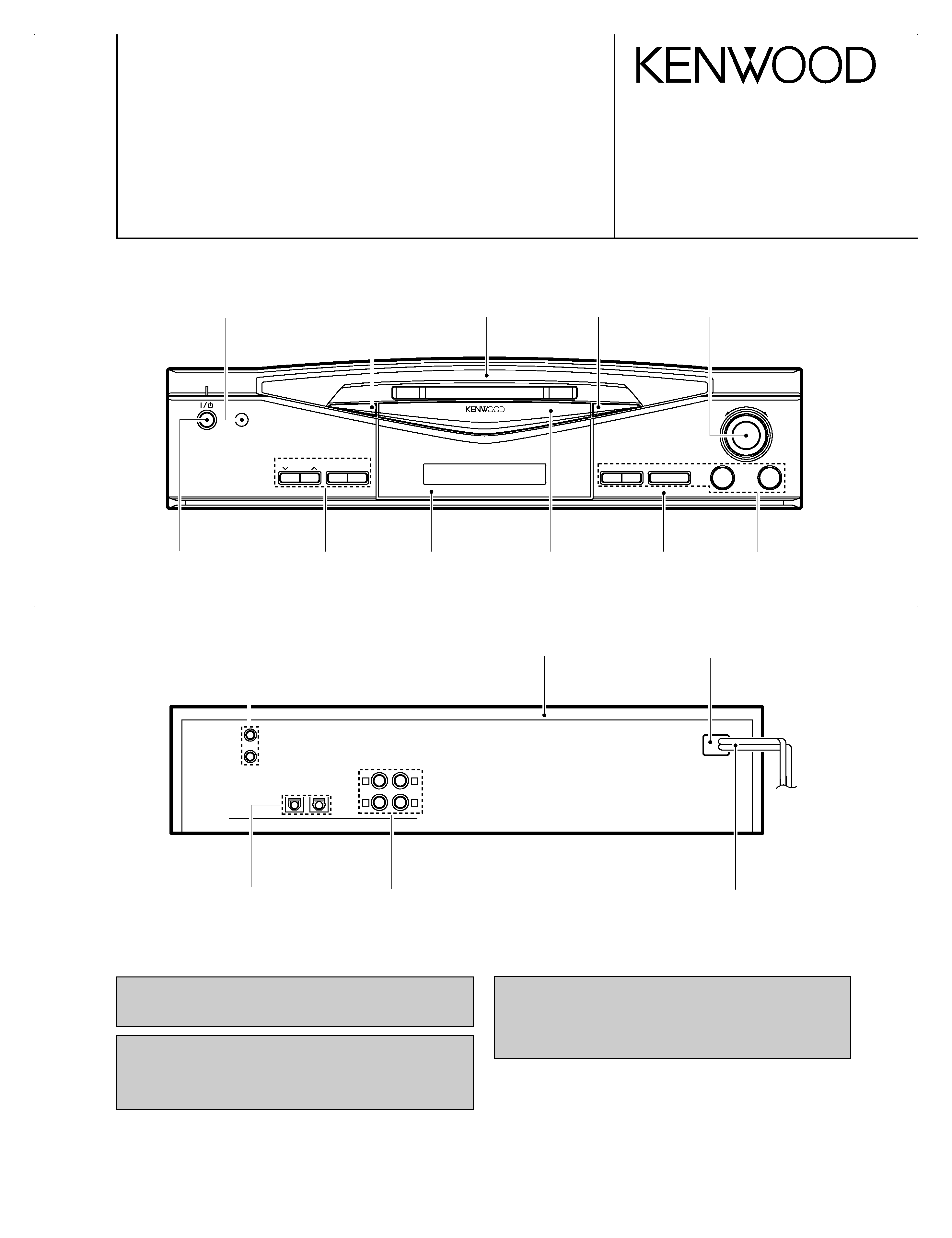
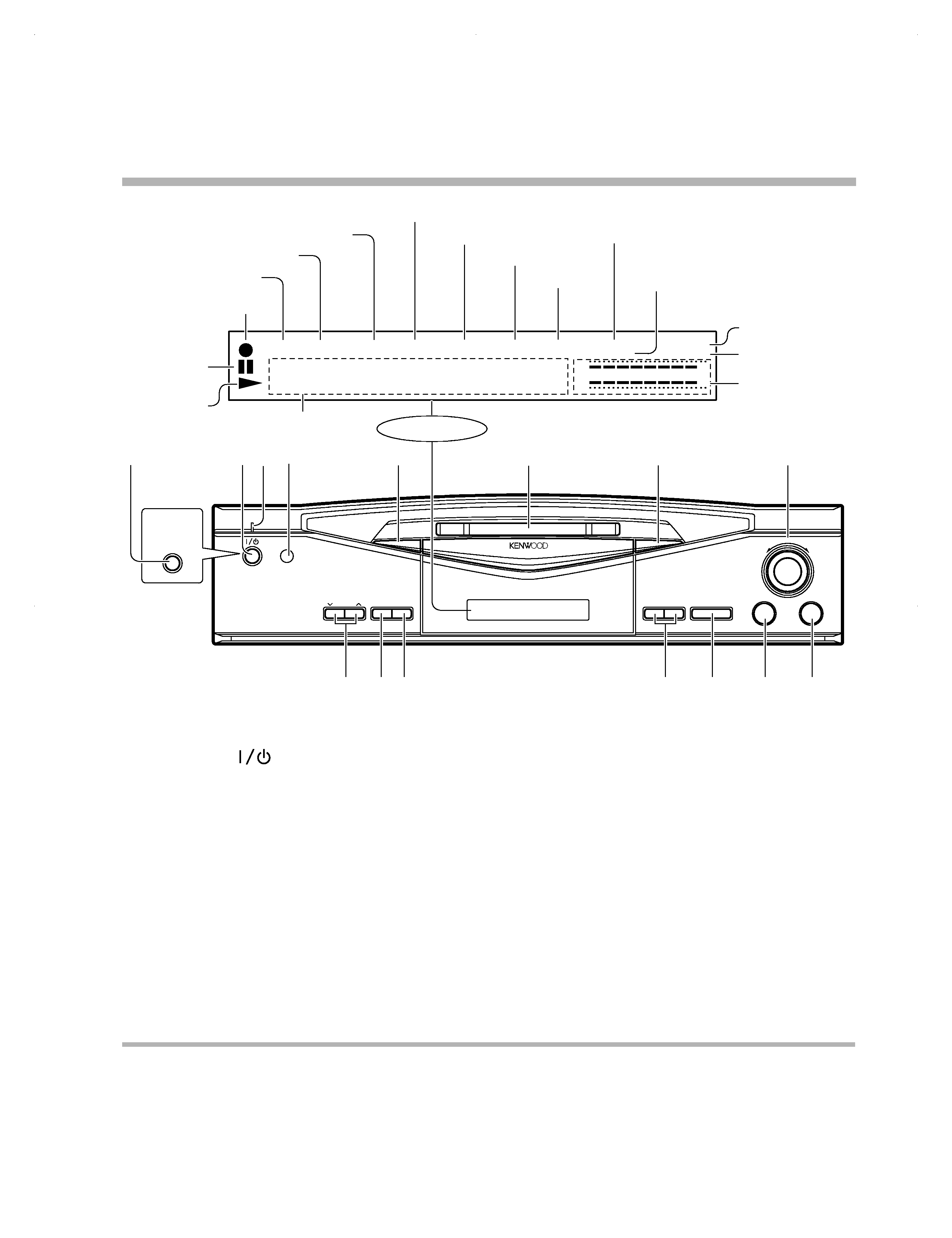
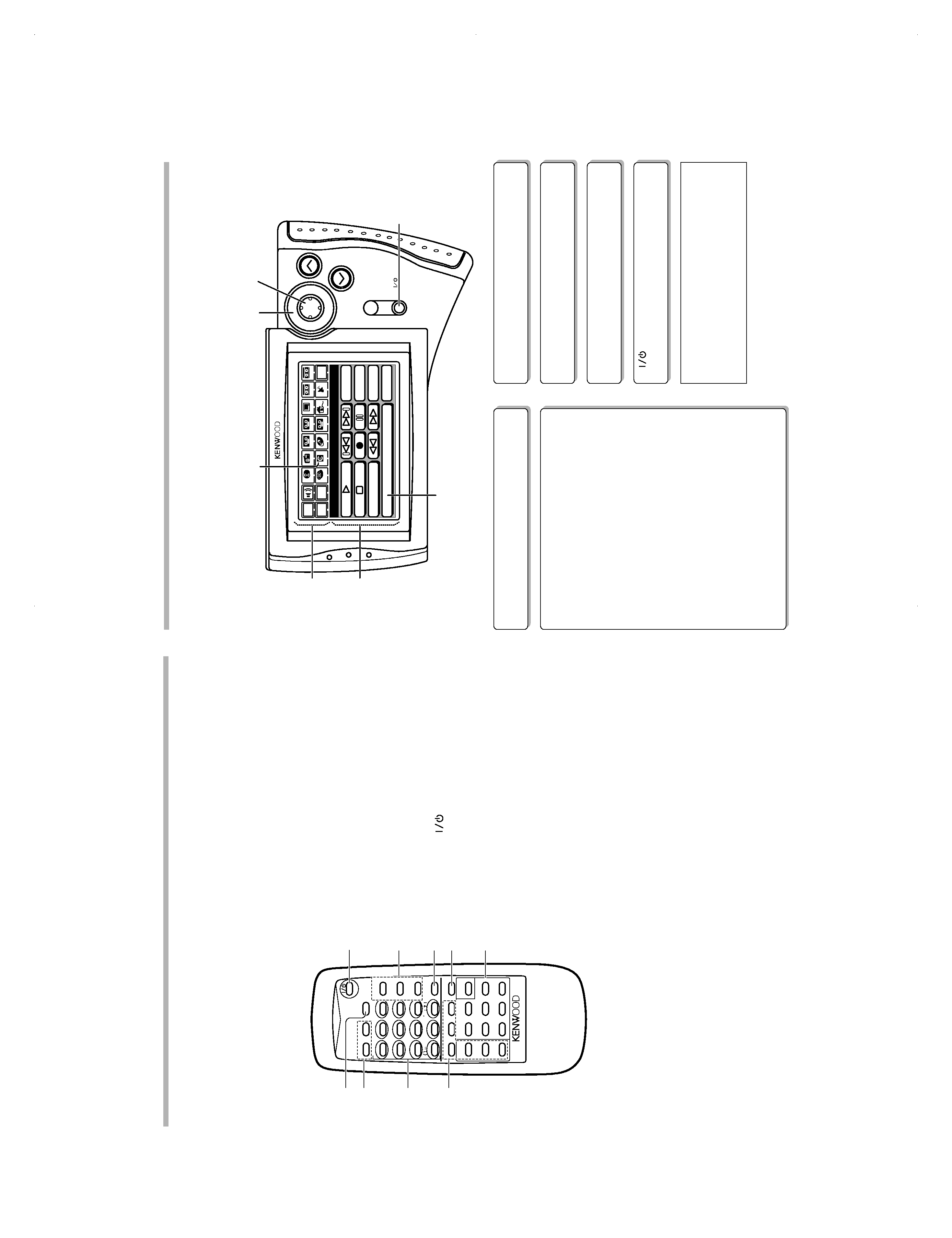
KENWOOD DM-S500 Service Manual

Cover page of KENWOOD DM-S500 Service Manual

Service Manual for KENWOOD DM-S500, downloadable as a PDF file.

Manual details

  • Immediate download after payment.
  • Delivered as a PDF file.
  • The manual has 24 pages
  • File size: 1.85 MB
  • Available language versions: English
  • Different language versions may vary sligthly in file size and page count.

We guarantee that...

  • our manuals are complete,
  • the manual includes circuit diagrams,
  • our manuals are checked with antivirus,
  • We'll issue refund if the manual is damaged, incomplete or unreadable (our refund policy)

Sample pages

Thumbnail of page 1Thumbnail of page 2Thumbnail of page 3Thumbnail of page 4
Thumbnail of page 5Thumbnail of page 6Thumbnail of page 7Thumbnail of page 8
Thumbnail of page 9
background image
* Refer to parts list on page 25.
Refer to DM-SE7/SE9 (B51-5395-00) and
DM-5090/9090 (B51-5387-00) service manu-
als if require circuit description.
MINI DISC RECORDER
DM-S500
SERVICE MANUAL
© 1997-11/B51-5398-00 (K/K) 2456
7
3
8
¡
1
÷REC
REC
INPUT
REC
LEVEL
ON/STANDBY
MINI DISC RECORDER DM-S500
0
TIME
DISPLAY
¢
4
L
R
L
R
REC
IN
DIGITAL IN
LINE
OPTICAL
1
2
PLAY
OUT
SYSTEM
CONTROL
Dressing panel
(A21-3620-02)
Dressing panel
(A21-3622-03)
Dressing panel
(A21-3623-03)
Dressing panel
(A21-3621-03)
Indicator
(B12-0329-04)
Miniature phone jack
(E11-0188-05)
AC power cord *
(E30-)
Optic receiving module
(W02-1181-05)
Power cord bushing
(J42-0083-05)
Phono jack
(E68-0120-05)
Metallic cabinet
(A01-3444-01)
Front glass
(B10-2386-12)
Knob
(K29-6835-12)
Knob
(K29-6835-12)
Knob
(K29-6835-12)
Knob
(K29-6945-04)
Panel *
(A60-)
In compliance with Federal Regulations, following are reproduc-
tions of labels on, or inside the product relating to laser product
safety.
KENWOOD-Crop. certifies this equipment conforms to DHHS
Regulations No. 21 DFR 1040. 10, Chapter 1, Subchapter J.
DANGER : Laser radiation when open and interlock defeated.
AVOID DIRECT EXPOSURE TO BEAM
DM-S500(K) COVER( 98.4.24 9:35 PM y[W 2
background image
Audio cord (2)
System control cord (1)
Optical
(E30-0505-05)
(E30-2733-05)
(B19-1529-05)
fiber cable (1)
Remote control unit (1)
Batteries (2)
AC
(A70-1187-05)
(E03-0115-05)
plug adaptor (1)
Use to adapt the plug on
the power cord to the
shape of the wall outlet.
(Accessory only for regions
where use is necessary.)
Battery cover (A09-0356-08)
DM-S500
2
CONTENTS / ACCESSORIES / CAUTIONS
CONTENTS / ACCESSORIES / CAUTIONS ...............2
CONTROLS .................................................................3
ADJUSTMENT ............................................................ 5
PC BOARD ............................................................... 10
SCHEMATIC DIAGRAM ............................................13
EXPLODED VIEW .....................................................23
PARTS LIST...............................................................25
SPECIFICATIONS .......................................Back cover
Accessories
Contents
Note related to transportation and movement
Before transporting or moving this unit, carry out the
following operations.
1. With no disc loaded in the unit, press the ON/STANDBY
key to on.
÷ Check that no disc is present in the unit.
2. Wait a few seconds and verify that the display shown
appears.
3. Press the ON/STANDBY key to off (standby).
(
-dB)
N O I D I S C
R
L
3
0
1
30 10 5
Cleaning
Unplug this appliance from the wall outlet before cleaning. Do not use
volatile solvents such as alcohol, paint thinner, gasoline, or benzine,
etc. to clean the cabinet. Use a clean dry cloth.
Caution against contact revitalizer
Do not use contact cleaners because it could cause a malfunction. Be
specially careful against contact cleaners containing oil, for they may
deform the plastic componente.
Maintenance
Cautions
DM-S500(K) COVER( 98.4.24 9:35 PM y[W 3
background image
DM-S500
3
CONTROLS
7
3
8
¡
1
÷REC
REC
INPUT
REC
LEVEL
ON/STANDBY
MINI DISC RECORDER DM-S500
0
TIME
DISPLAY
¢
4 SHUTTLE
REPEAT
(
- dB)
MANUAL
REMAIN
TOTAL
SINGLE
TITLE
· · · · · · · · · ·
R
L ··
3
0
1
30 10 5
SEARCH
PGM
DIGITAL 1 2
CD TEXT
MONITOR
ON/STANDBY
POWER
3
2
4
7
5
6
1
1
8 9 0
#
$
@
!
Play indicator
Character information display
Pause indicator
REC indicator
Peak level indicator
MANUAL indicator
Display / Main unit
REPEAT indicator
SINGLE indicator
PGM indicator
TOTAL indicator
REMAIN indicator
TITLE indicator
SEARCH
indicator
DIGITAL input indicator
Display
MONITOR indicator
For U.S.A.
and Canada
1 ON/STANDBY (
) key
Press to turn the unit on or off (standby).
1 POWER key (For U.S.A. and Canada)
Press to turn the unit on or off.
2 Standby indicator
3 Remote control sensor
The key control signals from the remote control unit enter the
main unit from here.
4 TIME DISPLAY key
5 Mini Disc insertion slot
Insert a minidisc.
6 Eject (0) key
Press to unload the Mini Disc.
7 SHUTTLE (4, ¢) knob
Use to skip disc tracks during playback.
During editing, this knob is used to select track numbers, title
and characters.
8 REC LEVELkeys
This key is used to adjust the recording level.
9 REC INPUT key
This key is used to switch the recording input source.
0 REC (¶) key
Press when starting recording.
! Fast forward and fast backward (1, ¡)
During playback, this key is used to move the played position
forward or backward.
At the time of editing, the cursor movement and the selected title
can be confirmed.
@ Pause (8) key
Press to temporary stop the disc operation.
# Stop (7) key
Press to stop the disc operation.
$ Play (3) key
Press to start playback.
About the STANDBY mode
While the STANDBY indicator is lit on the display, a small amount of power is supplied to the system to back up the memory. This is called the
standby mode. Under that condition, the system can be turned ON by the remote control unit.
CD TEXT indicator
DM-S500(K) COVER( 98.4.24 9:35 PM y[W 6
background image
DM-S500
4
CONTROLS
Remote controlunit
1 TIME DISPLAY key
: Press to switch the time display mode.
2 Applied operation keys
RAMDOM key
: Used at the time of random playback.
REPEAT key
: Press to play tracks repeatedly.
3 Numeric keys
: Press to specify the desired track number.
: Used at the time of title input for selection of characters and
symbols.
4 Edit operation keys
EDIT key
: This key is used to switch the editing mode.
SET key
: Press to set the editing result or input title definitely in memory.
ENTER key
: Press to execute editing or title input operation.
TITLE INPUT key
: This key is used to switch the title input mode.
TITLE SEARCH key
: This key is used to switch the title search mode.
EDIT CANCEL key
: Used to cancel editing.
5 POWER (
) key
: Press to turn the unit on or off (standby).
6 Program operation keys
P.MODE (Play mode)/CHARACTER key
: This key is used in program playback. During title input, it is used to
select the character group.
CHECK/SPACE key
: This key is used to check the program contents.
During title input, it is used to insert a blank space character.
CLEAR/DELETE key
: This key is used to clear the program. During title input, it is used to
delete a character.
7 REC INPUT (Recordinginput) key
: This key is used to switch the recording input source.
8 MONITOR key
: The sound of the unit connected to "DIGITAL 2" is heard.
9 Basic operation keys
1 ¡ : Fast forward and fast backward keys.
(Same function as the keys on the main unit.)
4 ¢ : Skip keys.
(Same function as the knob on the main unit.)
¶ : Record key
8 : Pause key
7 : Stop key
3 : Play key
AUTO/MANU. key
: This is used for selection of automatic (AUTO) or manual (MANU.)
track number assignment at the time of recording.
Model: RC-M0502
Infrared ray system
CURSOR/CHECK
RANDOM
REPEAT
TIME
DISPLAY
ABC
DEF
1
2
3
P.MODE
CHARACTER
GHI
JKL
MNO
4
5
6
CHECK
SPACE
PRS
TUV
WXY
7
8
9
CLEAR
DELETE
POWER
QZ
,
+100
0
+10
REC
INPUT
EDIT
SET
ENTER
MONITOR
TITLE
INPUT
CURSOR/CHECK
AUTO/
MANU.
TITLE
SEARCH
4
¢
EDIT
CANCEL
7
3
1
¡
8
REMOTE CONTROL UNIT
&
/
RC-M0502
1
2
6
7
8
3
4
9
5
1Segment screen
This screen is used for selecting the icons for the main equip-
ment.
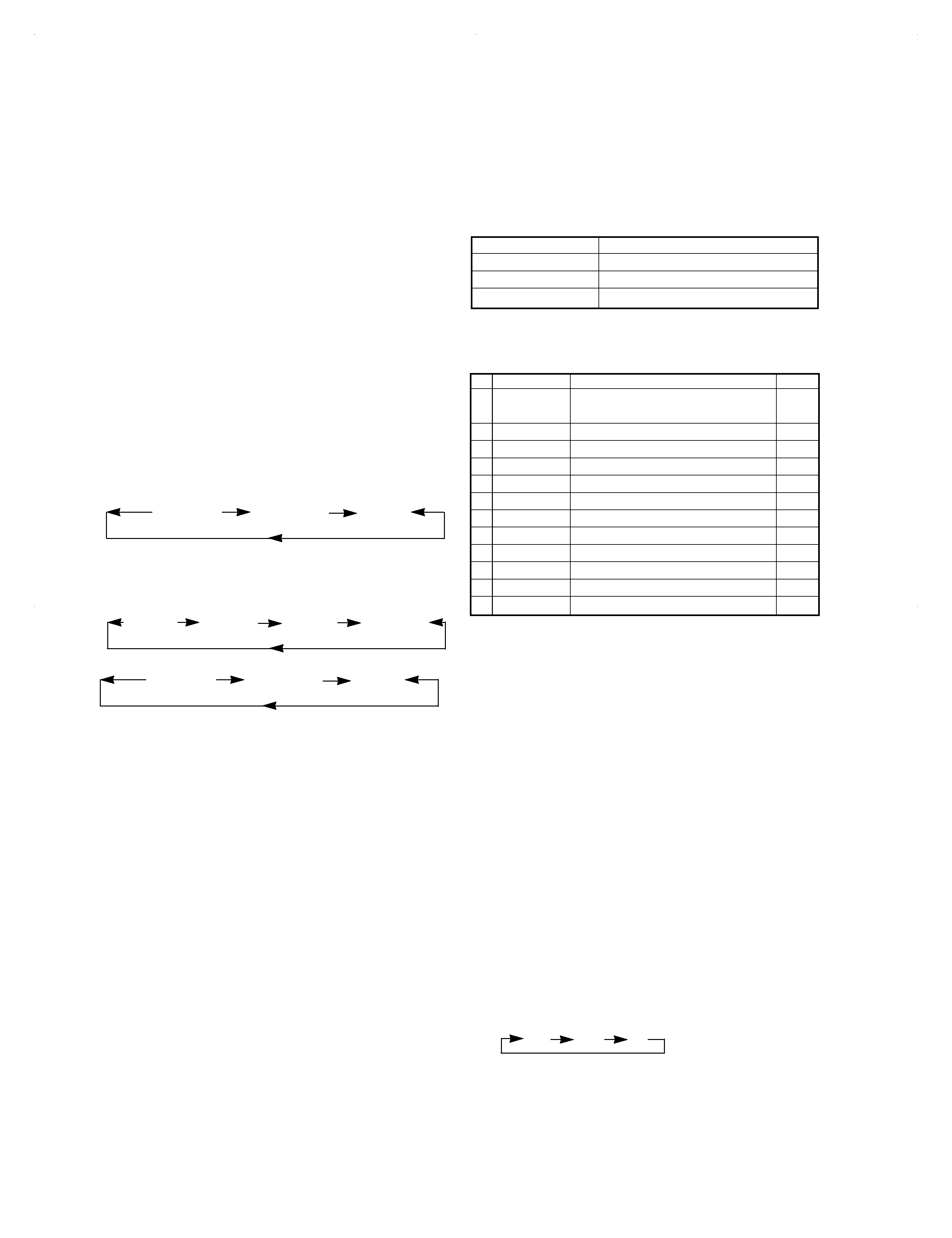
Graphical Remote Control Unit (GRC)
REMOTE CONTROL UNIT
ON /STANDBY
MUTE
VOLUME
ENTER
Return
VCR2
VCR1
TV
Sat.
Cable
TapeB
TapeA
Confirm
Tape1
LD
MD
DVD
Tuner
CD
Set Up
Main
Menu
MD
Edit
Mode
PGM
10key
Power
Title Search
2
1
3
6
5
4
3
Model : GRC-151, GRC-102 or
GRC-101
Infrared ray system
A graphical remote control (GRC-151, GRC-102 or GRC-101) is sold separately.
To enable remote control operation, simply connect this unit, cassette deck (sold separately), and other accessories to the AV
CONTROL CENTER with the system control cords.
2Menu screen
This screen is used for selecting the icons for the operating modes.
MD recorder operation panel
Play icon (
3)
Pause icon (
8)
Stop icon (
7)
Search icons (
1, ¡)
These icons send the track forward or backward.
Mode icon
This icon is used to select the playback mode.
Skip icons (
4, ¢)
When selected, the next track in the icon direction is played.
10key Pad icon
This icon switches to the Numeric Icon menu screen.
Power icon
This icon is used to turn the unit on or off. You can use this icon
only when you select "IR" in the setup menu.
Rec icon (
¶)
This icon is used for recording.
PGM icon
This icon is used for program playback.
Edit icon
This icon is used to select the editing mode.
Title Search icon
This icon is used to switch the title search mode.
3Icons
Icons for the equipment used and operating mode are displayed.
4Joystick
The joystick is used when selecting the icons.
(Lightly press the edge of
5.)
5ENTER key
Press this button to input the selected icon (operation mode, and
so on).
6
(ON/STANDBY) key
This key turns ON/STANDBY this unit or the equipment con-
nected with the system control cords.
If your GRC unit is the GRC-100 or GRC-150
If the GRC unit provided with your AV CONTROL CENTER
(optional) or receiver (optional) is the "GRC-100" or "GRC-
150", the DM-S500 unit should be controlled using the
remote control unit provided with this unit.
DM-S500(K)
COVER(
98.4.24
9:35
PM
y[W
7
background image
No.
Display
Description
Section
1
TEMP ADJU
The work of adjustment is unnecessary
-
in this mode
2
LDPWR ADJU
Laser power adjustment
3-5
3
LDPWR CHEC
Laser power check
3-5
4
EFBAL ADJU
Traverse adjustment
3-6
5
FBIAS ADJU
Focus bias adjustment
3-7
6
CPLAY MODE
Continuous playback mode
2-4-1
7
CREC MODE
Continuous recording mode
2-4-2
8
STT-LIMIT
Check the mechanism start limit SW position
-
9
JUMP MODE
Track jump checking mode
-
10 SRV DATA RE
Servo data reading
-
11 EEP MODE
E2PPROM data reading or rewrite
-
12 EEP INITIA
E2PROM data initializing
-
1. Test mode of the unit
1-1 Setting of the test mode
While pressing the [STOP] key, plug the AC power cord
into the AC wall outlet.
1-2 Contents of the test mode
1 [DOT TEST]
2 [SEG TEST]
0 3 [KEY TEST]
0 4 [CYBER TEST] J type only
0 Used for production line only
1-3 Function of the test mode
1 [DOT TEST]
The FL display starts the "NIAGARA MODE" by pressing
the [PLAY] key in the [DOT TEST] mode.
2 [SEG TEST]
Turn the FL indication ON by pressing the [PLAY] key in
the [SEG TEST] mode.
The FL indication changes cyclically as shown in the
below by turning the SHUTTLE (
4¢).
1-4 Function of the key
1 SHUTTLE (
¢) and down (4)keys
: Selects the test mode.
: Selects the FL indication
2 Play key
: Proceeds the test mode or return to test mode.
3 Stop key
: Cancel the test mode.
1-5 Microprocessor reset
The microprocessor can be initialized while pressing the
[EJECT] key, plug the AC power cord into the AC wall
outlet.
2. Mechanism test mode
2-1 Setting the test mode
While pressing the [PLAY] key, plug the AC power cord into
the AC wall outlet
2-2 Canceling the test mode
Unplug the AC power cord.
1. Test mode of the unit
2-3 Basic operation in test mode
All operations are performed using the SHUTTEL
(up/down), PLAY key and STOP key. The functions of each
key are shown in the table below.
2-4 Selection of test mode
12 test modes are selected by turning the SHUTTLE.
For more information on each adjustment mode, refer to
each section of 3, "Electrical adjustment".
If other adjustment mode has been entered incorrectly,
press the STOP key to exit the mode.
* The number 8 - 12 are not used for service. If these
mode have been entered incorrectly, press the STOP
key immediately to exit the mode. Specially, do not use
EEP INITIAL. (E2PROM data has initialized if used it.)
2-4-1 Operation in continuous playback mode
1. Entering the continuous playback mode
(1) Insert a recordable disc or pre-mastered disc into the
unit.
(2) Turn the SHUTTLE to display "CPLAY MODE".
(3) Press the PLAY key. The display then changes from
"CPLAY MODE" to "CPLAY MID".
(4) After the access operation is completed, the display
changes from "CPLAY MID" to "C=#### a=##".
Note: Numerals on the display appear the error rate and
ADIP error.
2. Change the playback point.
(1) Press the PLAY key during continuous playback. The
display then changes as follows.
MID
OUT
IN
(2) After the access operation is completed, the display
changes "C=####" a=##".
[DOT TEST]
[SEG TEST]
[KEY TEST]
[CYBER TEST]
5
ADJUSTMENT
DM-S500
FL LIGHT ON
FL LIGHT OFF
ENGLISH
FL LIGHT ON
FL LIGHT OFF
ENGLISH
Function
Description
SHUTTEL (up/down) Changes the parameter and mode.
PLAY key
Proceeds for definition.
STOP key
Returns for interrupt.
DM-S500 EXP 98.4.26 2:41 PM y[W 1

Reviews

There are no reviews of this manual yet.