Audio
(E30-0505-05)
cord .................... (2)
AC
(E03-0115-05)
plug adaptor........... (1)
System
(E30-2816-05)
control cord ... (1)
(Except for Europe and Australia)
For the unit with an European AC
plug in areas other than Europe.
CT-401/403/KXF-W1030/W3030
2
CONTENTS / ACCESSORIES
CONTROLS
CONTENTS / ACCESSORIES .................................. 2
CONTROLS ................................................................2
CIRCUIT DESCRIPTION ............................................3
ADJUSTMENT ............................................................4
PC BOARD ................................................................ 5
SCHEMATIC DIAGRAM ............................................ 7
EXPLODED VIEW ....................................................12
PARTS LIST..............................................................13
SPECIFICATIONS ......................................Back cover
Contents
Accessories
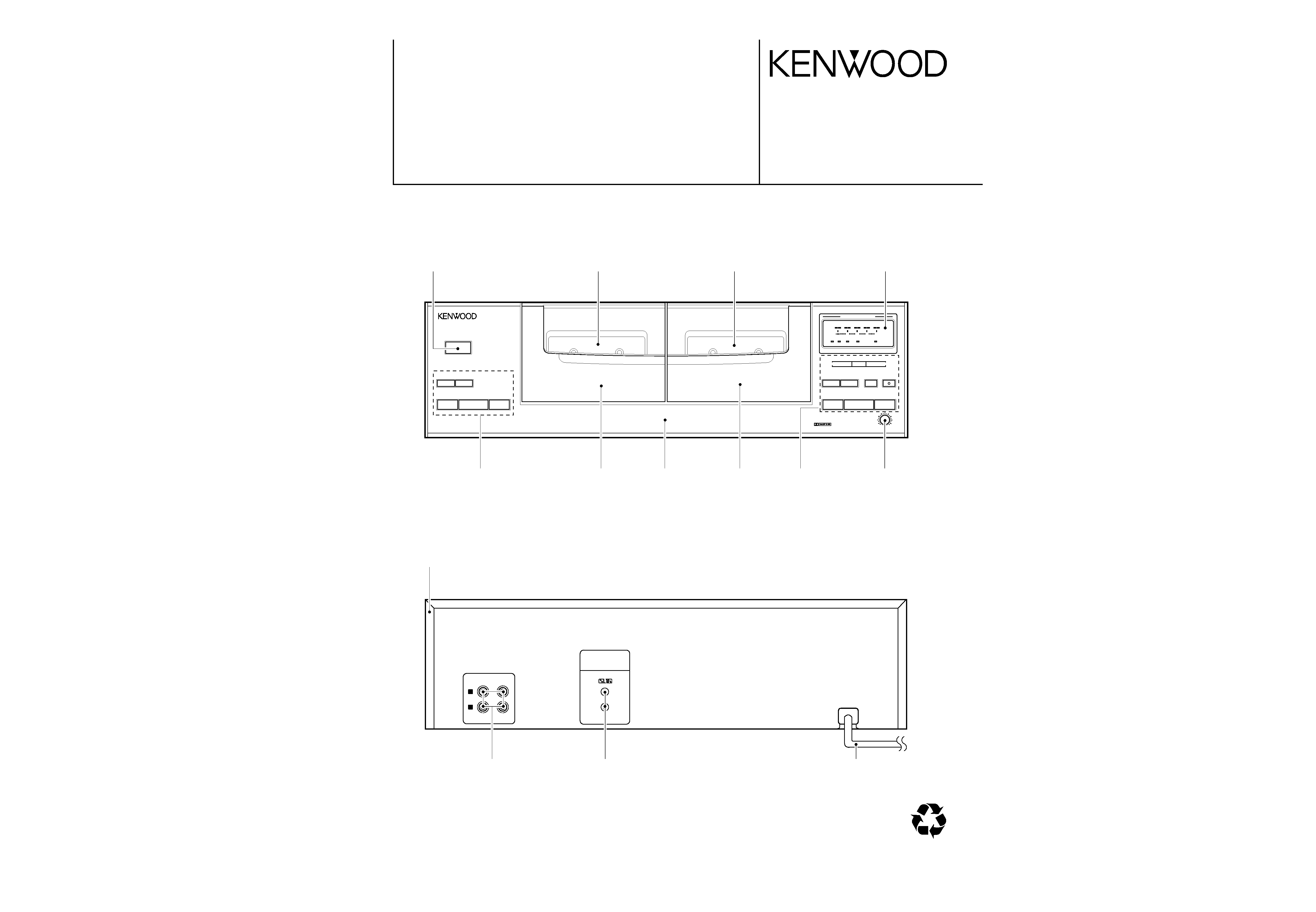
DISPLAY
DOLBY NR reference level
(dB)
--5
0+3
+6
(dB)
DPSS
TAPE
B
TAPE
A
POWER
- ON OFF
1
3
7
3
7
¡
18PAUSE ¶REC/ARM
¡
REC LEVEL
MIN
MAX
PUSH/OPEN
0
PUSH/OPEN
0
DOLBY NR
DUBBING
DUBBING
DOLBY NR
(dB)
--5
0
+3
+6
(dB)
DUBBING
DOLBY NR
PEAK LEVEL METER
PEAK LEVEL METER
FULL LOGIC CONTROL
FULL LOGIC CONTROL
21
0
34
5
6 7
8
9
!@
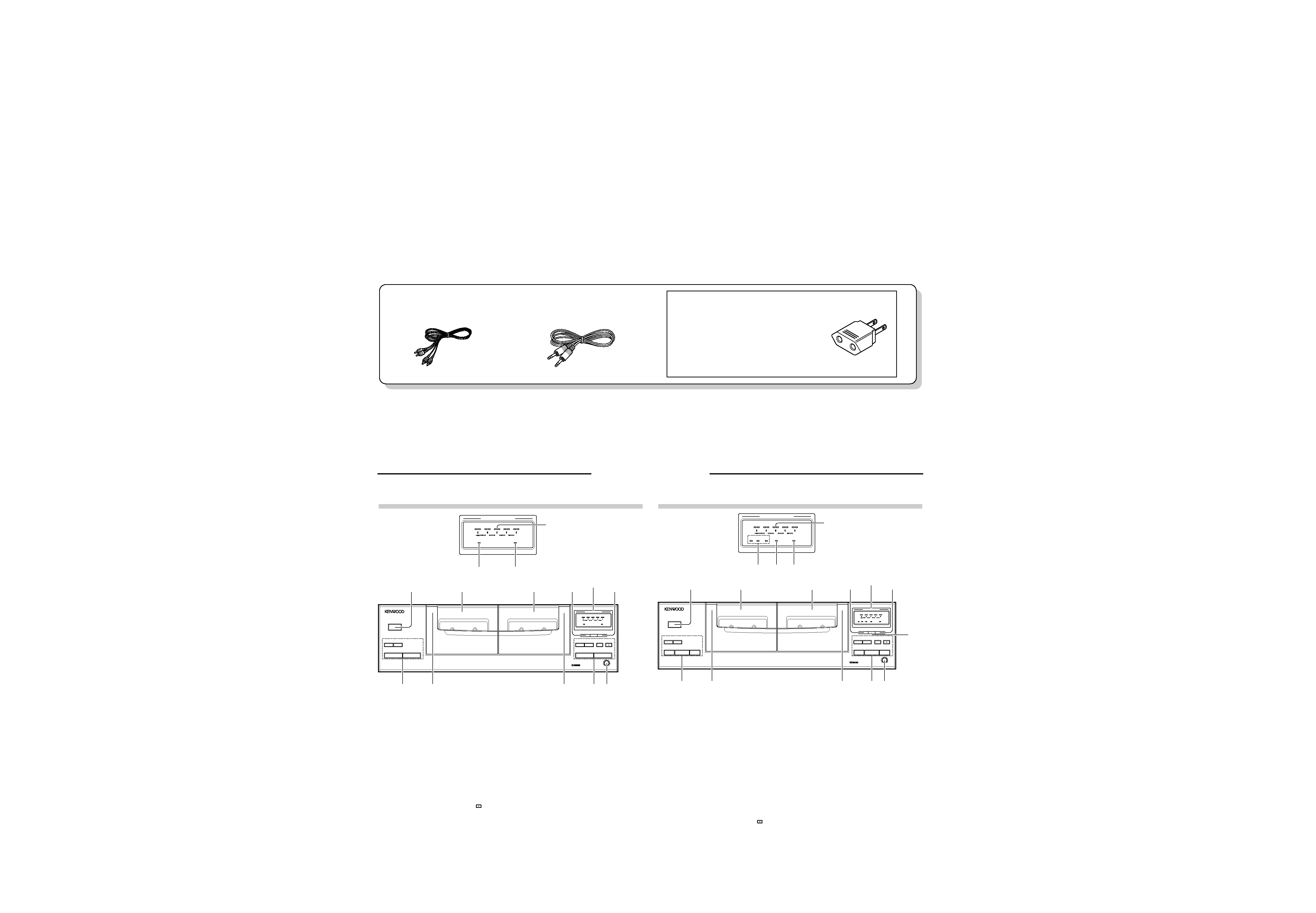
DISPLAY
1 Deck A
Playback-only tape deck.
2 POWER switch:
Press to turn power
- ON and OFF.
3 Deck A operation keys
3 key :
Play key.
1 key:
Rewind key. (for fast winding of tape
toward the left reel seen from you)
33 key:
Fast forward key (for fast winding of
tape toward the right reel seen from
you)
7 key:
Stop key.
4 Cassette holder (Deck A)
Press the area marked "PUSH/OPEN
0" to load or eject a tape.
5 Cassette holder (Deck B)
Press the area marked "PUSH/OPEN
0" to load or eject a tape.
6 Deck B operation keys
3 key :
Play key.
1 key:
Rewind key (for fast winding of tape
toward the left reel seen from you)
33 key:
Fast forward key (for fast winding of
tape toward the right reel seen from
you)
7 key:
Stop key
¶ REC/ARM key:
Press in stop mode to start recording
or press in record mode to let the
recording pause after leaving a non-
recorded blank of 4 seconds.
indicator : (Recording indicator)
8PAUSE key:
Press to let recording pause temporarily.
7 REC LEVEL control:
Adjusts the recording level.
8 DUBBING key:
Press to start tape dubbing.
9 DOLBY NR key:
Press to select the Dolby Noise Reduction
mode.
0 Deck B
Tape deck which is capable of both
playback and recording.
! DOLBY NR indicator
@ DUBBING indicator
1 Deck A
Playback-only tape deck.
2 POWER switch:
Press to turn power
- ON and OFF.
3 Deck A operation keys / indicators
@ , # keys : (Play keys)
@ , # indicators : (direction indicators)
Tapes are played in the directions
indicated by their respective indicators.
1 key:
Rewind key (for fast winding of tape
toward the left reel seen from you)
33 key:
Fast forward key (for fast winding of
tape toward the right reel seen from
you)
7 key:
Stop key
4 Cassette holder (Deck A)
Press the area marked "PUSH/OPEN
0" to load or eject a tape.
5 Cassette holder (Deck B)
Press the area marked "PUSH/OPEN
0" to load or eject a tape.
6 Deck B operation keys
@ , # keys : (Play keys)
@ , # indicators : (direction indicators)
Tapes are played in the directions
indicated by their respective indicators.
1 key:
Rewind key (for fast winding of tape
toward the left reel seen from you)
33 key:
Fast forward key (for fast winding of
tape toward the right reel seen from
you)
7 key:
Stop key
¶ REC/ARM key:
Press in stop mode to start recording
or press in record mode to let the
recording pause after leaving a non-
recorded blank of 4 seconds.
indicator : (Recording indicator)
8PAUSE key:
Press to let recording pause temporarily.
7 REC LEVEL control:
Adjusts the recording level.
8 DOLBY NR key:
Press to select the Dolby Noise Reduction
mode.
9 DUBBING key:
Press to select the DUBBING mode.
0 REV.MODE key:
Press to select the REVERS mode.
! Deck B
This deck is capable of both playback and
recording.
@ Reverse mode indicators
# DOLBY NR indicator
$ DUBBING indicator
DISPLAY
DOLBY NR reference level
DISPLAY
(dB)
--5
0+3
+6
(dB)
DPSS
TAPE
B
AUTO REVERSE
TAPE
A
AUTO REVERSE
POWER
- ON OFF
1
@#
7
@#
7
¡
18PAUSE ¶REC/ARM
¡
REC LEVEL
MIN
MAX
PUSH/OPEN
0
PUSH/OPEN
0
REV.MODE DOLBY NR
DUBBING
DUBBING
DOLBY NR
p
O
(dB)
--5
0
+3
+6
(dB)
DUBBING
DOLBY NR
p
O
2
34
5
6 7
8
9
0
@#$
1
!
PEAK LEVEL METER
PEAK LEVEL METER
CT-401/KXF-W1030
CT-403/KXF-W3030