1050MD/DM-5090/DM-9090
2
CONTENTS/ACCESSORIES/CAUTIONS
CONTENTS/ACCESSORIES/CAUTIONS ...................2
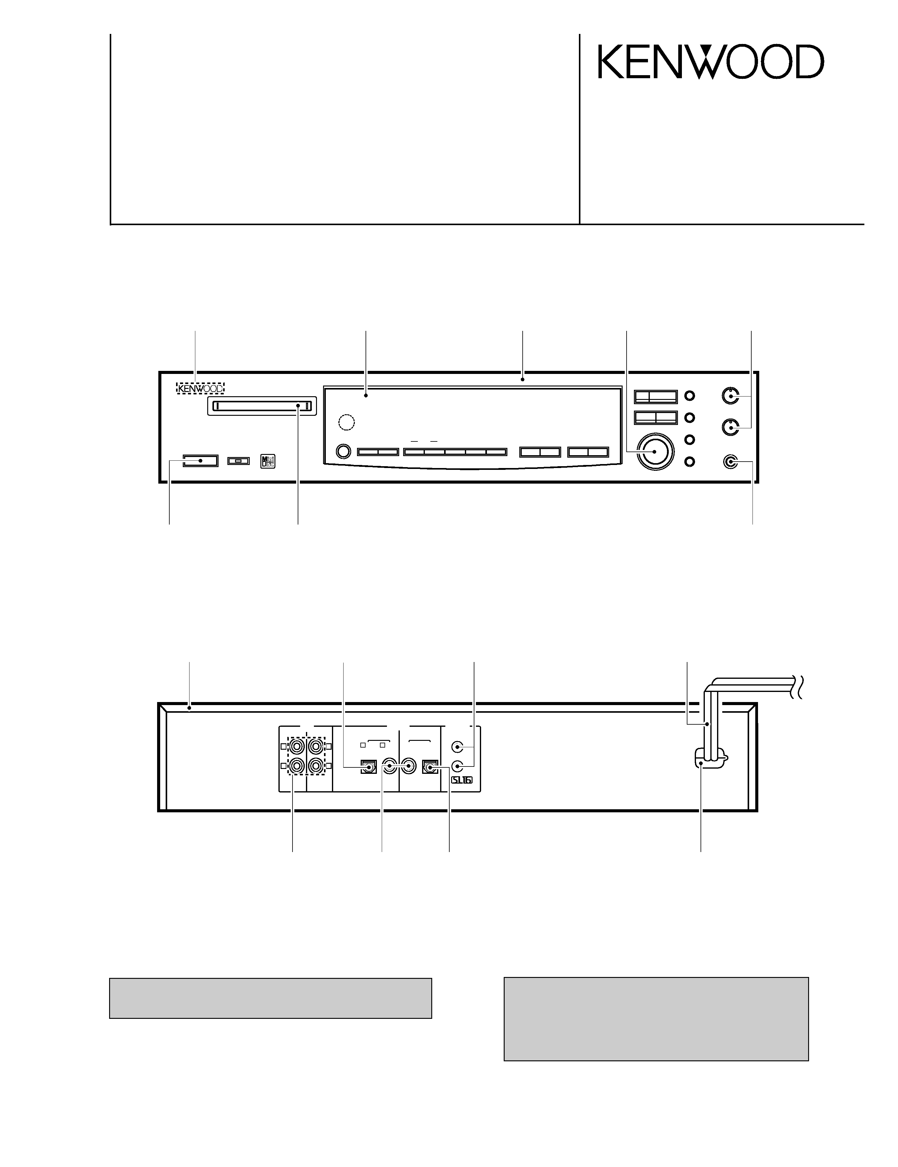
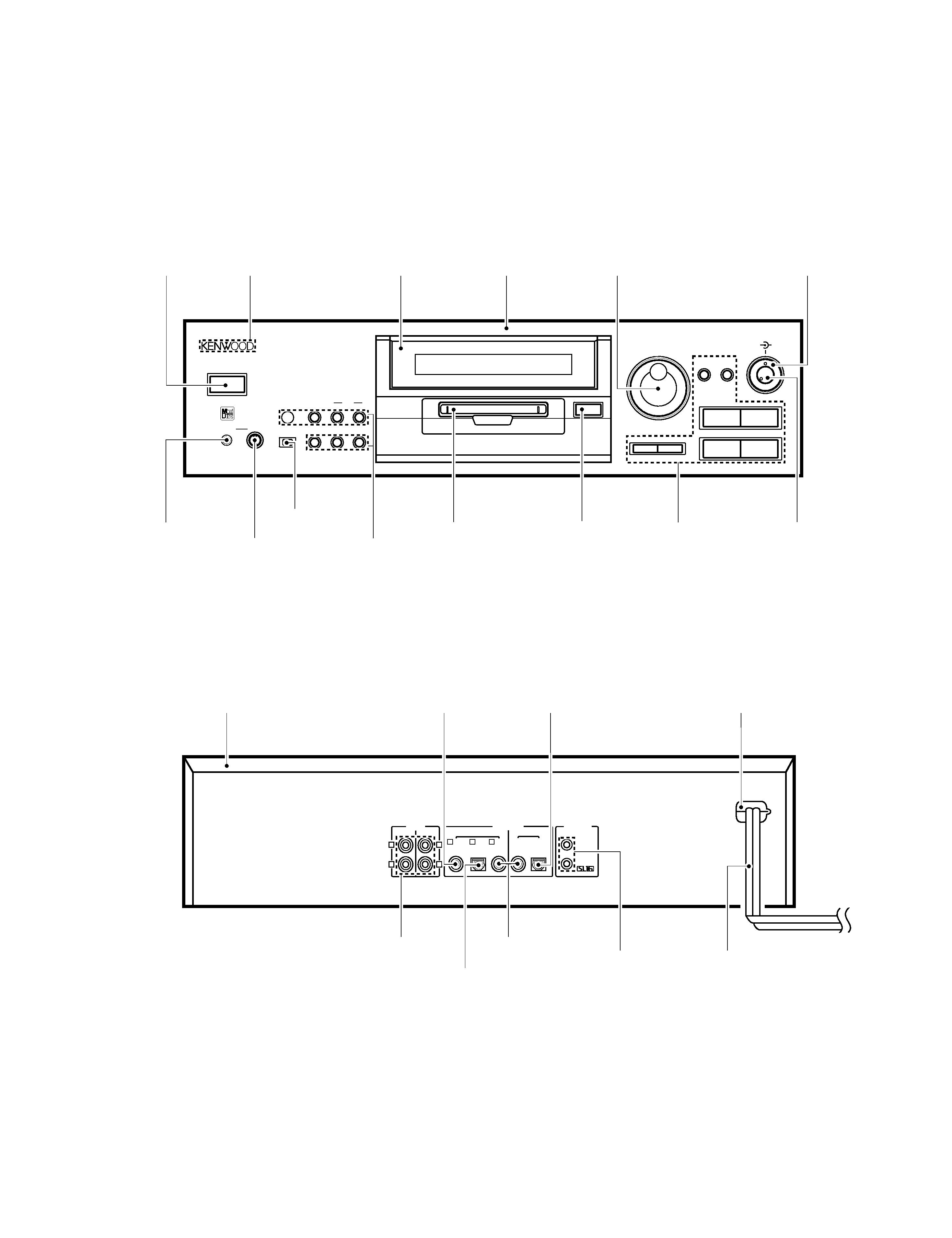
EXTERNAL VIEW ........................................................3
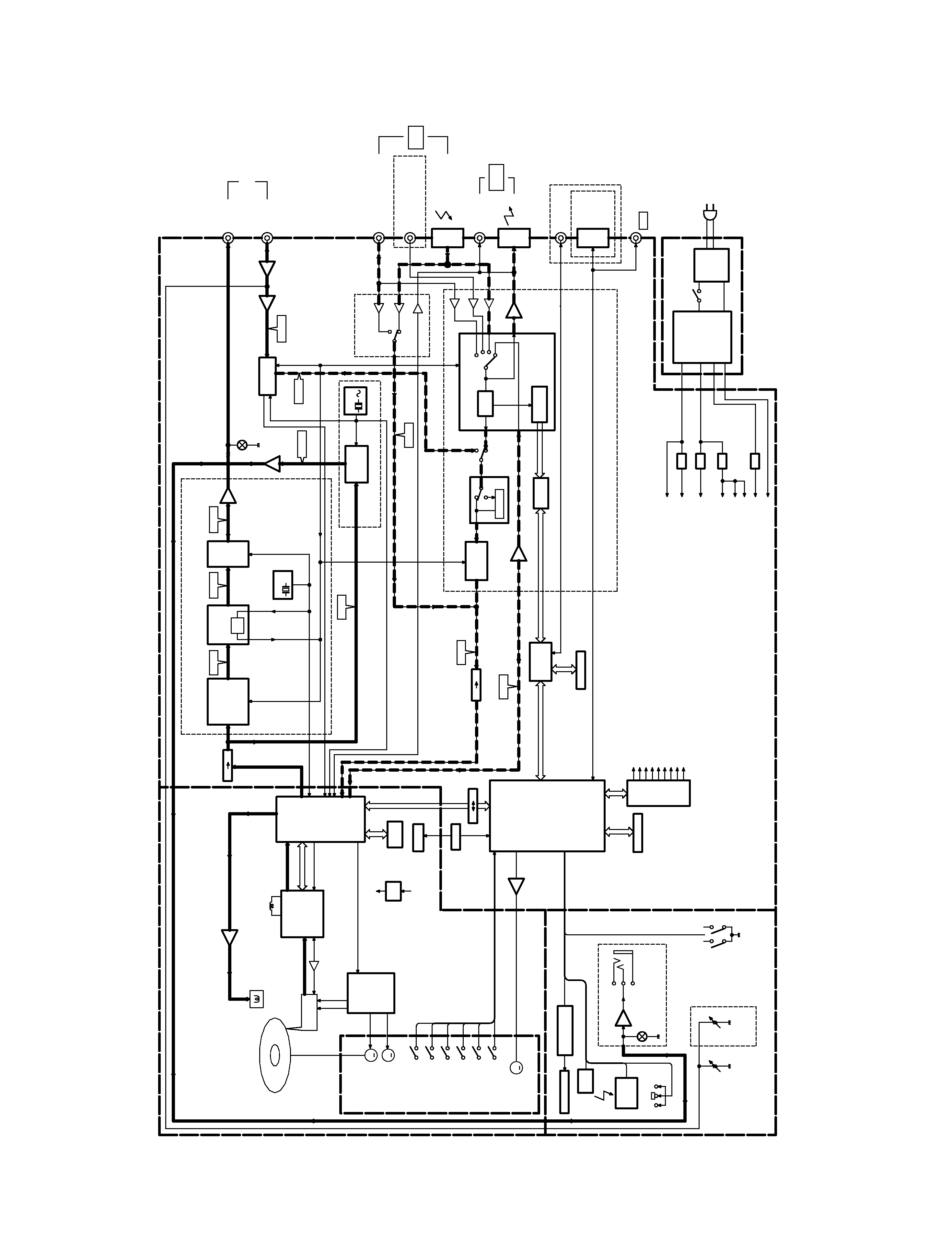
BLOCK DIAGRAM .......................................................4
CIRCUIT DESCRIPTION .............................................5
WIRING DIAGRAM ....................................................14
PC BOARD ............................................................... 15
SCHEMATIC DIAGRAM ........................................... 21
EXPLODED VIEW .....................................................37
PARTS LIST...............................................................40
SPECIFICATIONS .....................................................49
CONTENTS
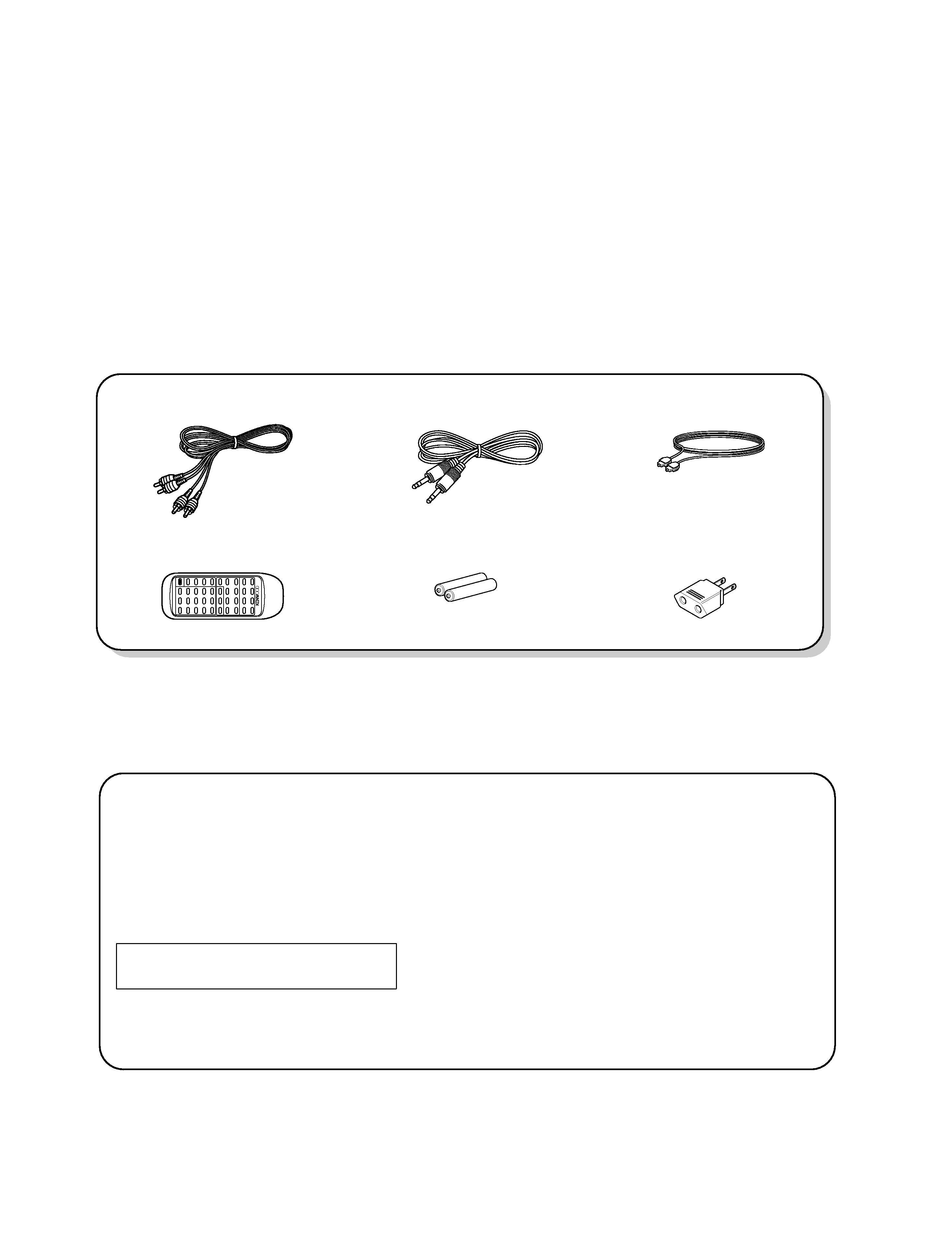
Accessories
System control cord (1)
(E30-2733-05)
Remote control unit (1)
(A70-1141-05: RC-M0702)
Battery cover: (A09-0362-08)
Batteries (R6/AA) (2)
Audio cord (2)
(E30-0505-05)
Optical fiber cable(1)
(B19-1529-05)
Note related to transportation and movement
Before transporting or moving this unit, carry out the
following operation.
1. Set the POWER key to ON without loading a Mini Disc.
÷ Check that no disc is present in the unit.
2. Wait a few seconds and verify that the display shown
appear.
3. Set the POWER key to OFF.
N O
D I S C
Beware of condensation
When water vapor comes into contact with the surface of
cold material, water drops are produced.
If condensation occurs, correct operation may not be possi-
ble, or the unit may not function correctly.
This is not a malfunction, however, the unit should be dried.
(To do this, turn the POWER switch ON and leave the unit
as it is for several hours.)
Be especially careful in the following conditions :
When the unit is brought from a cold place to a warm place,
and there is a large temperature difference.
When a heater starts operating.
When the unit is brought from an air-conditioned place to a
place of high temperature with high humidity.
When there is a large difference between the internal tem-
perature of the unit and the ambient temperature, or in con-
ditions where condensation occurs easily.
AC adaptor (1)
(E03-0115-05)
M type only
Cautions
1050MD/DM-5090(K) COVER 97.11.28 2:25 AM
y[W 3