DENON DP-500M Owner's Manual

Cover page of DENON DP-500M Owner's Manual

Owner's Manual for DENON DP-500M, downloadable as a PDF file.

Manual details

  • Immediate download after payment.
  • Delivered as a PDF file.
  • The manual has 8 pages
  • File size: 1.03 MB
  • Available language versions: English
  • Different language versions may vary sligthly in file size and page count.

We guarantee that...

  • our manuals are complete,
  • our manuals are checked with antivirus,
  • We'll issue refund if the manual is damaged, incomplete or unreadable (our refund policy)

Sample pages

Thumbnail of page 1Thumbnail of page 2Thumbnail of page 3Thumbnail of page 4
Thumbnail of page 5Thumbnail of page 6Thumbnail of page 7Thumbnail of page 8
Thumbnail of page 9
background image
OPERATING INSTRUCTIONS
DIRECT DRIVE MANUAL TURNTABLE SYSTEM
DP-500M
SERIAL NO.
PLEASE RECORD UNIT SERIAL NUMBER ATTACHED TO THE REAR OF THE
CABINET FOR FUTURE REFERENCE
background image
OPERATING INSTRUCTIONS
DIRECT DRIVE MANUAL TURNTABLE SYSTEM
DP-500M
SERIAL NO.
PLEASE RECORD UNIT SERIAL NUMBER ATTACHED TO THE REAR OF THE
CABINET FOR FUTURE REFERENCE
background image
2
IMPORTANT TO SAFETY
CAUTION:
1.
Handle the power supply cord carefully.
Do not damage or deform the power supply cord. If it
is damaged or deformed, it may cause electric shock
or malfunction when used. When removing from wall
outlet, be sure to remove by holding the plug attach-
ment and not by pulling the cord.
2.
Do not open the bottom cover
In order to prevent electric shock, do not open the bot-
tom cover.
If problems occur, contact your DENON dealer.
3.
Do not place anything inside
Don not place metal objects or spill liquid inside the
turntable system.
Electric shock or malfunction may result.
Please, record and retain the Model name and serial
number of your set shown on the rating label.
Model No. DP-500M
Serial No.
WARNING:
TO PREVENT FIRE OR SHOCK HAZARD, DO NOT
EXPOSE THIS APPLIANCE TO RAIN OR MOISTURE.
· Caution:
Whenever the turntable is in the "STOP" position, the
unit is still connected on AC line voltage.
Please be sure to unplug the cord when you leave
home for, say, a vacation.
CAUTION
RISK OF ELECTRIC SHOCK
DO NOT OPEN
CAUTION:
TO REDUCE THE RISK OF ELECTRIC SHOCK, DO
NOT REMOVE COVER (OR BACK). NO USER-
SERVICEABLE PARTS INSIDE. REFER SERVICING
TO QUALIFIED SERVICE PERSONNEL.
The lightning flash with arrowhead symbol, within an
equilateral triangle, is intended to alert the user to the
presence of uninsulated "dangerous voltage" within the
product's enclosure that may be of sufficient magnitude
to constitute a risk of electric shock to persons.
The exclamation point within an equilateral triangle is
intended to alert the user to the presence of important
operating and maintenance (servicing) instructions in
the literature accompanying the appliance.
This device complies with Part 15 of the FCC Rules. Operation is subject to
the following two conditions: (1) This device may not cause harmful
interference, and (2) this device must accept any interference received,
including interference that may cause undesired operation.
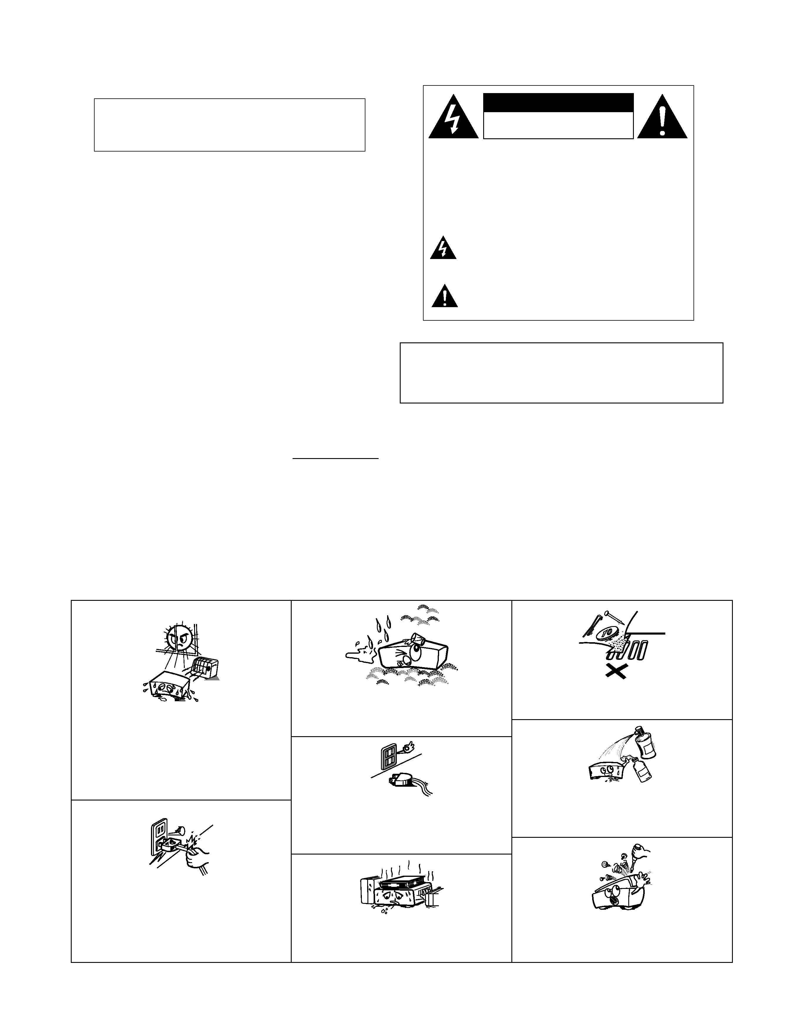
NOTE ON USE
·Avoid high temperatures.
Allow for sufficient heat dispersion when
installed on a rack.
· Eviter des températures élevées
Tenir compte d'une dispersion de chaleur
suffisante lors de l'installation sur une étagère.
· Handle the power cord carefully.
Hold the plug when unplugging the cord.
· Manipuler le cordon d'alimentation avec
précaution.
Tenir la prise lors du débranchement du cordon.
· Keep the set free from moisture, water, and
dust.
·Protéger l'appareil contre l'humidité, l'eau et
lapoussière.
· Unplug the power cord when not using the set
for long periods of time.
· Débrancher le cordon d'alimentation lorsque
l'appareil n'est pas utilisé pendant de longues
périodes.
* (For sets with ventilation holes)
· Do not obstruct the ventilation holes.
· Ne pas obstruer les trous d'aération.
· Do not let foreign objects in the set.
· Ne pas laisser des objets étrangers dans
l'appareil.
· Do not let insecticides, benzene, and thinner
come in contact with the set.
· Ne pas mettre en contact des insecticides, du
benzène et un diluant avec l'appareil.
· Never disassemble or modify the set in any
way.
· Ne jamais démonter ou modifier l'appareil
d'une manière ou d'une autre.
background image
3
Thank you very much for purchasing the DENON direct drive
manual turntable system.
Please read the operating instructions thoroughly in order to
acquaint yourself with the turntable system and achieve max-
imum satisfaction from it.
TABLE OF CONTENTS
FEATURES ......................................................................3
1. PART NAMES AND FUNCTIONS ..............................3
2. ASSEMBLY.................................................................4
3. ADJUSTMENTS .........................................................5
4. CONNECTIONS .........................................................6
5. OPERATION...............................................................6
6. TROUBLESHOOTING................................................7
7. MAIN SPECIFICATIONS ............................................7
Please check to make sure the following items are
included with the main unit in the carton:
(1)
Operating instructions (these instructions)...............1
(2)
Turntable ..................................................................1
(3)
Turntable sheet.........................................................1
(4)
Counterweight ..........................................................1
(5)
45 rpm record adapter..............................................1
(6)
Head shell ................................................................1
(7)
Hinge ........................................................................2
(8)
Dust cover ................................................................1
(9)
Connecting cord .......................................................1
FEATURES
1. High Rotational Performance
A high degree of rotational performance has been
achieved through the use of a high-performance, high-
torque direct drive motor, speed detection using a high-
density optical pulse encoder, and a PLL quartz control
system, etc.
2. Hybrid (2-Layer) Platter Offers Excellent Vibration
Resistance
The bottom surface of the large-sized, thick aluminum
die cast platter is entirely covered with a silicon rubber
sheet which increases the internal vibrational losses
and prevents platter ringing.
3. Rubber Mat Developed with Holographic Analysis Tech-
nology
Close adhesion of the record with the surface of the
turntable mat is necessary in attaining a stable sound.
The surface of the turntable mat has a minute taper from
the outside portion to the inside portion which increases
the adhesive qualities of the record.
4. Finely Finished Wooden Cabinet
The large-sized wooden cabinet incorporates the latest
technology in both the materials and the finish. A large-
sized insulator is used that comprises a combination of
damping rubber and conical springs to strike a balance
between howling characteristics and elegance.
z
z
z
z Power button
OFF, ¢ON)
· When the power is switched ON, the orange LED of the
speed selector button is illuminated. The orange LED is
illuminated at 33-1/3 rpm and the green LED at 45 rpm.
x
x
x
x Speed selector button
(33-1/3: Orange LED lights up. 45: Green LED lights up.)
· Set this button according to the record's playing speed.
For 33-1/3 rpm records ..............33
For 45 rpm records ....................45
1. PART NAMES AND FUNCTIONS
c
c
c
c START/STOP button
Press this button to start and stop the turntable.
v
v
v
v Lock nut
· Use this to install the head shell.
b
b
b
b Tone arm
n
n
n
n Arm rest
· This is the tone arm support.
m
m
m
m Lifter lever
· Use this to lift and lower the tone arm.
,
,
,
, ANTI-SKATING knob
· When the record is playing, a force is generated drawing
the stylus towards the center of the record. Set this knob
to the same value as the stylus pressure to offset this
force.
.
.
.
. Stylus pressure adjustment ring
· Use this to adjust the stylus pressure.
/
/
/
/0000 Counterweight
· Use this to balance the tone arm and to adjust the stylus
pressure.
/
/
/
/1111 Dust cover
· Use this to protect important records from dust and dirt.
Keep the dust cover closed when not using the player.
background image
4
· Do not plug in the power cord until assembly is com-
pleted.
(1) Mounting the turntable
Remove all the parts in the box.
Remove the packaging materials from the main unit
and all the parts.
· Set the parts on the floor, a table or another stable
surface when removing the packaging materials.
Handling the parts roughly could result in scratches
or deformation.
Insert the turntable onto the motor shaft.
· Be careful not to scratch the magnet ring on the bot-
tom side of the turntable.
Set the turntable sheet on the turntable, lining it up
with the motor shaft.
(2) Mounting the counterweight.
Mount the counterweight on the shaft at the back of
the tone arm.
2. ASSEMBLY
Turntable sheet
Turntable
Motor shaft
1
2
3
4
1
(3) Mounting the cartridge
· The cartridge is not included.
Mount your cartridge on the head shell.
· The head shell's lead wires are color-coded. Use
tweezers or the like to securely connect the lead
wires to the corresponding terminals on the cartridge,
referring to the indications on the cartridge or the car-
tridge's instructions.
Red .......................... right channel (R)
White........................ left channel (L)
Green ....................... right channel ground (RG)
Blue.......................... left channel ground (LG)
·A predetermind overhang will be obtained, if it
attaches so that the needle point may come to the
position of 54mm from head shell attachement
edge(rubber washer part) as shown in the following
figure.
Insert the head shell on which the cartridge has
been mounted into the tone arm and fasten it in
place using the lock nut.
(4) Mounting the dust cover
Securely insert the two included hinges into the
holder in the rear of the cabinet.
Line up with the hole of dust cover with the hinges
and insert it securely in the direction of the arrows.
·To remove the dust cover, open it fully and pull it out
of the hinges in the opposite direction of the arrows.
· Hold the dust cover near the hinges when mounting
and removing it.
1
54mm
head shell
cartridge
(sold separately)
2
OUTPUT
RL
GND
Holder
Hinge
1
2
background image
5
·Turn the power off when performing adjustments.
(1) Stylus pressure and anti-skating adjustment
Set the anti-skating knob to "0".
Lower the lifter lever, and move the tone arm.
· Lift the tone arm from the armrest and move it over
the turntable.
· When moving the tone arm, lower the cartridge's sty-
lus cover and be careful that the stylus does not
directly touch the turntable or other parts.
·For cartridges with detachable stylus covers, adjust
with the stylus cover removed.
Adjust the horizontal balance.
·Move the counterweight
forward or backward so
that the tone arm is par-
allel to the turntable's
surface when the tone
arm is released.
· When adjusting the horizontal balance, be careful
that the stylus does not touch the turntable sheet or
the main unit.
Set the tone arm back on the armrest.
3. ADJUSTMENTS
1
2
3
Set parallel
4
Hold
the
counterweight
with a finger so that it does
not move, then turn the sty-
lus
pressure
adjustment
ring so that the back center
line on the back of the tone
arm is at "0".
Turn the counterweight in the direction of the arrow
A and set it for the proper stylus pressure for the
cartridge you are using.
· When the counterweight is turned, the stylus pres-
sure adjustment ring also turns. Read the value on
the adjustment ring to set the proper stylus pressure.
· Please refer to the instruction manual of the cartridge
for set stylus pressure.
Turn the anti-skating knob and set it so that the
value of the cartridge's stylus pressure is lined up
with the reference line.
· This provides the proper
anti-skating force.
0.5
0
1.0
1.5
2.0
2.5
3.5
3.0
5
6
7
A
N
T
I-S
KATING
0
1
2
3

Reviews

There are no reviews of this manual yet.