- 2 -
PP-2515L-C
If extended damage is caused due to negligence during
repair, the legal responsibility shall be with the repairing
company.
3. Check for safety after repair.
Check that the screws, parts and wires are put back se-
curely in their original position after repair. Ensure for safety
reasons there is no possibility of secondary ploblems
around the repaired spots.
If extended damage is caused due to negligence of repair,
the legal responsibility shall be with the repairing company.
4. Caution in removal and making wiring connection to the
parts for the automobile.
Disconnect the battery terminal after turning the ignition
key off. If wrong wiring connections are made with the bat-
tery connected, a short circuit and/or fire may occur. If ex-
tensive damage is caused due to negligence of repair, the
legal responsibility shall be with the repairing company.
5. Cautions regarding chips.
Do not reuse removed chips even when no abnormality is
observed in their appearance. Always replace them with
new ones. (The chip parts include resistors, capacitors,
diodes, transistors, etc). The negative pole of tantalum
capacitors is highly susceptible to heat, so use special care
when replacing them and check the operation afterwards.
6. Cautions in handling flexible PWB
Before working with a soldering iron, make sure that the
iron tip temperature is around 270 . Take care not to ap-
ply the iron tip repeatedly(more than three times)to the
same patterns. Also take care not to apply the tip with force.
CAUTIONS
Use of controls,adjustment,or performance of procedures
other than those specified herein,may result in hazardous
radiation exposure.
The compact disc player should not be adjusted or repaired
by anyone except properly qualified service personnel.
7. Turn the unit OFF during disassembly and parts replace-
ment. Recheck all work before you apply power to the unit.
8. Cautions in checking that the optical pickup lights up.
The laser is focused on the disc reflection surface through
the lens of the optical pickup. When checking that the la-
ser optical diode lights up, keep your eyes more than 30cms
away from the lens. Prolonged viewing of the laser within
30cms may damage your eyesight.
9. Cautions in handling the optical pickup
The laser diode of the optical pickup can be damaged by
electrostatic charge caused by your clothes and body. Make
sure to avoid electrostatic charges on your clothes or body,
or discharge static electricity before handling the optical
pickup.
9-1. Laser diode
The laser diode terminals are shorted for transporta-
tion in order to prevent electrostatic damage. After
replacement, open the shorted circuit. When remov-
ing the pickup from the mechanism, short the termi-
nals by soldering them to prevent this damage.
9-2. Actuator
The actuator has a powerful magnetic circuit. If a
magnetic material is put close to it. Its characteris-
tics will change. Ensure that no foreign substances
enter through the ventilation slots in the cover.
9-3. Cleaning the lens
Dust on the optical lens affects performance. To
clean the lens, apply a small amount of isopropyl
alcohol to lens paper and wipe the lens gently.
ADJUSTMENT
Clock accuracy
FM noise
convergence
1. Turn off and on the ACC switch, while holding CD-EJECT button and Power
button. Repeat it twice slowly.
2. Set a universal counter to TP201,adjust TC201 so that a reading of the counter
is 0+0.1/-0.1 sec./day.
Item
Procedure
Measuring
instrument
1. Input the 98.1MHz/55dBu(1kHz,30% MOD)signal.(VOL1.4V=0dB)
2. Adjust the outputs to -22+3/-3dB by VR102 when the SG output is set -20dBu.
Universal counter
SSG
Milli-volt meter
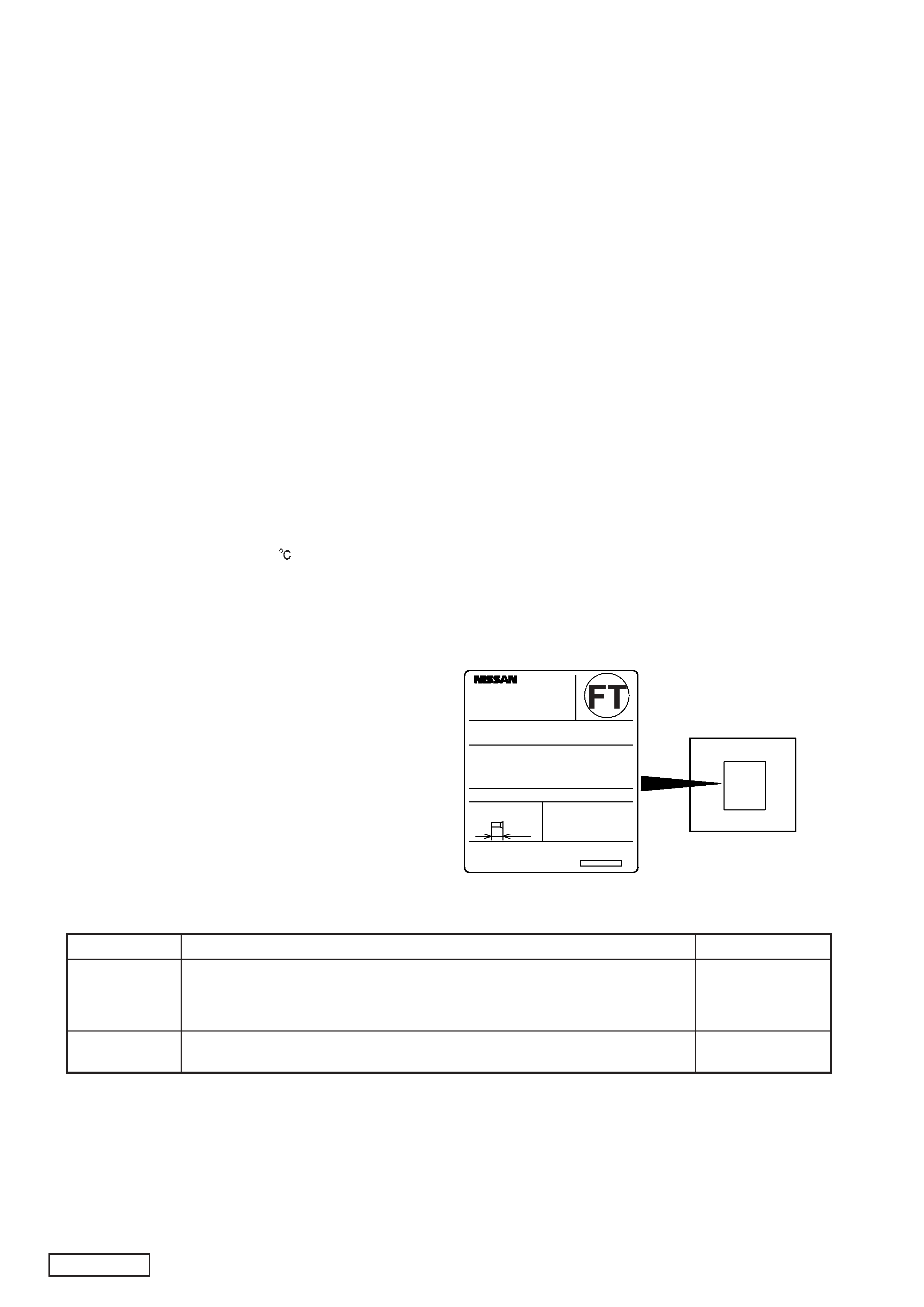
M O D E L
N O .
A M : 5 3 0 k H z - 1 7 1 0 k H z
I S O
( F L AT MACHI NE SCREW)
M 5
P A R T
N o .
C l a r i o n
C o . , L t d
F M : 8 7 . 7 5 M H z - 1 0 7 . 9 M H z
F R E Q U E N C Y
R A N G E
T H I S
D E V I C E
C O M P L I E S
WI T H
P A R T
1 5
O F
T H E
F C C
R U L E S .
O P E R A T I O N
I S
S U B J E C T
T O
T H E
F O L L O WI N G
T WO
C O N D I T O I N S : ( 1 )
T H I S
D E V I C E
M A Y
N O T
C A U S E
H A R M F U L
I N T E R F E R E N C E , A N D ( 2 )
T H I S D E V I C E
M U S T
A C C E P T
A N Y
I N T E R F E R E N C E
R E C E I V E D , I N C L U D I N G
I N T E R F E R E N C E
T H A T
M A Y
C A U S E
U N D E S I R E D
O P E R A T I O N .
T H I S
P R O D U C T I O N
C O MP L I E S
WI T H
D H H S
R U L E S
2 1
C F R
S U B C H A P T E R
J
A P P L I C A B L E
A T
D A T E
O F
MA N U F A C T U R E .
M O U N T
S C R E W
M A N U F A C T U R E D
5 0
K A M I T O D A , T O D A
S H I , S A I T A M A
K E N , J A P A N
1 2 V ( - ) G R O U N D
S E R I A L
N O .
8 m m
M A X
PP-2515L
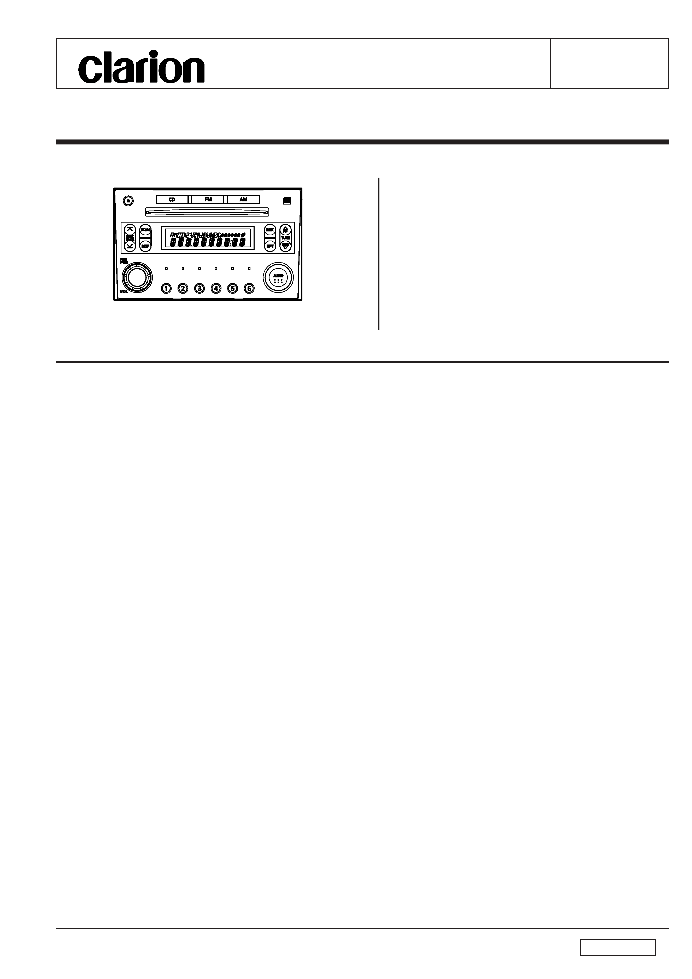
Top view of main unit