CLARION 28185 EH20A Service Manual

Cover page of CLARION 28185 EH20A Service Manual

Service Manual for CLARION 28185 EH20A, downloadable as a PDF file.

Manual details

  • Immediate download after payment.
  • Delivered as a PDF file.
  • The manual has 14 pages
  • File size: 1.59 MB
  • Available language versions: English
  • Different language versions may vary sligthly in file size and page count.

We guarantee that...

  • our manuals are complete,
  • the manual includes circuit diagrams,
  • our manuals are checked with antivirus,
  • We'll issue refund if the manual is damaged, incomplete or unreadable (our refund policy)

Sample pages

Thumbnail of page 1Thumbnail of page 2Thumbnail of page 3Thumbnail of page 4
Thumbnail of page 5Thumbnail of page 6Thumbnail of page 7Thumbnail of page 8
Thumbnail of page 9
background image
PN-2701B-B
- 1 -
Published by Service Dept.
Printed in Japan
Clarion Co., Ltd.
50 Kamitoda, Toda-shi, Saitama 335-8511 Japan
Service Dept.: 5-66 Azuma , Kitamoto-shi, Saitama 364-0007 Japan
Tel: +81-48-541-2335 / 2432 FAX: +81-48-541-2703
298-6xxx-00 Apr.2006
Service Manual
Model
NISSAN Genuine (BOSE Type)
Cockpit Module
AM/FM Radio Stereo
6-CD Changer Deck
PN-2701B-B
(Genuine No. 28185 EH20A)
(Xanavi Genuine No. CD6K-1211U)
original service manual.
DIFFERENCE FROM ORIGINAL
This unit supports the 16-figure display of Satellite radio.
IC402 Audio CPU different.
Parts that have been described to this manual have changed
for the performance improvement.
MODEL
COMPONENTS
PN-2714B-B
1.
Main unit
-----------
1
2.
Lock pin
966-0653-21
1
CAUTIONS
Use of controls,adjustment,or performance of procedures
other than those specified herein,may result in hazardous ra-
diation exposure.
The compact disc player should not be adjusted or repaired by
anyone except properly qualified service personnel.
ORIGINAL SERVICE MANUAL
This additional service manual is designed to be used
together with Model PN-2714B-A
This manual has described only the difference point with the
Originalmodel
Manual No.
PN-2714B-A
298-6224-00
Look pin
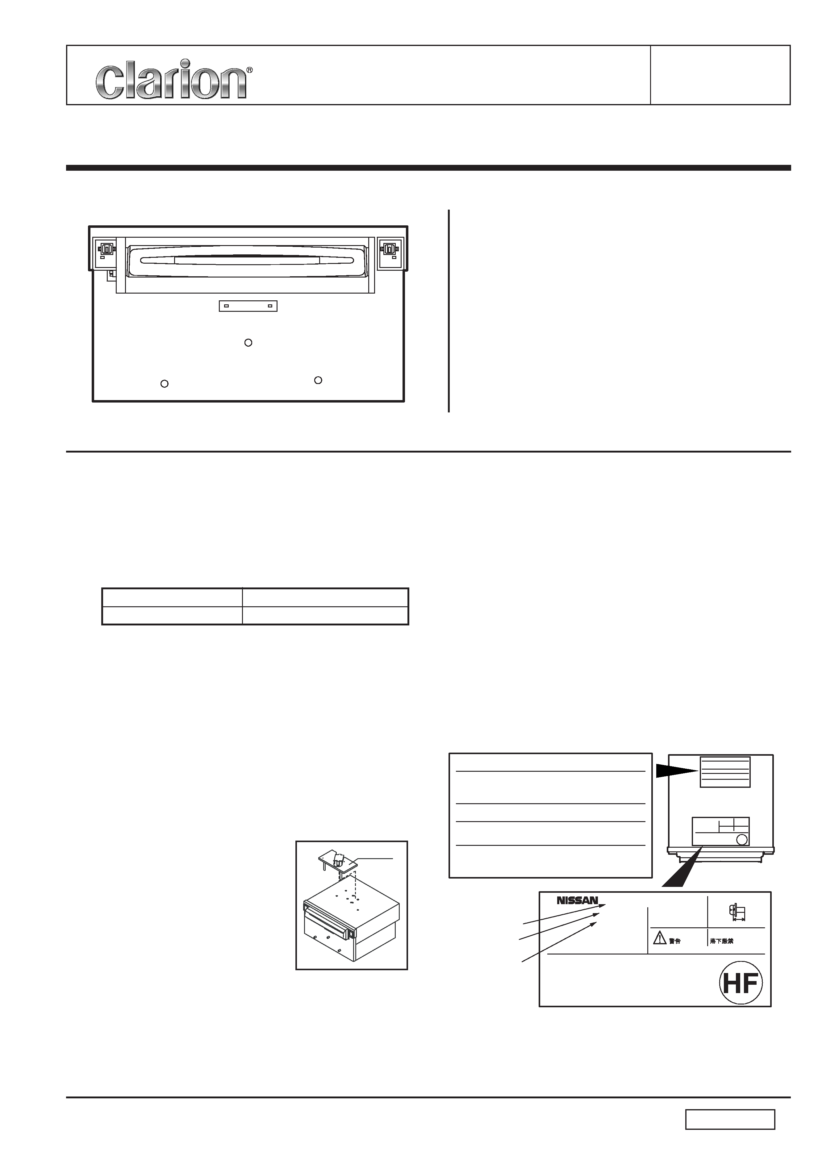
NOTE
*
In case that the main unit or the CD
changer mechanism is transported
for repair, the lock pin(966-0653-
21) must be set to fix the mecha-
nism assy.
*
We cannot supply PWB with com-
ponent parts in principle. When a
circuit on PWB has failure, please
repair it by component parts base. Parts which are not
mentioned in service manual are not supplied.
*
This product includes technology owned by Microsoft Cor-
poration and cannot be used or distributed without a li-
cense from MSLGP.
*
Specifications and design are subject to change without
notice for further improvement.
MANUFACTURED
.
DO NOT DROP
WARNING
MOUNT
S CRE W
M5 X 8
mm
MA X
FR E Q U E N C Y
R A N G E
A M :
530 - 1710 kHz
F M :
87.75 - 107.9 MHz
This product includes technology owned by Microsoft Corporation and
cannot be used or distributed without a license from MSLGP.
THIS PRODUCTION COMPLIES WITH DHHS RULES 21 CFR SUBCHAPTER J
APPLICABLE AT DATE OF MANUFACTURE.
THIS DEVICE COMPLIES WITH PA RT 15 OF THE FCC RULES, OPE
RATION IS SUBJECT TO THE FOLLOWING TWO CONDITIONS; (1)
THIS DEVICE MAY NOT CAUSE HARMFUL INTERFERENCE, AND (2)
THIS DEVICE MUST ACCEPT ANY INTERFERENCE RECEIVED, INCL
UDING INTERFERENCE THAT MAY CAUSE UNDESIRED OPERATION.
28185 EH200
PN-2701B
CD6K-1210U
Model No.
Xanavi No.
NISSAN No.
background image
PN-2701B-B
- 2 -
EXPLANATION OF IC
052-3188-83
M30853FHGP
Audio CPU
Terminal Description
pin
1: CTRST
: O : Contrast adjustment analogue output(DA).
pin
2: SPEED
: IN : Speed Pulse input.
pin
3: EEP/ST DA
:I/O: The serial data input/output for EEP and
Sub-tuner.
pin
4: EEP/ST CK
: O : The serial clock output for EEP and Sub-
tuner.
pin
5: BU DET
: IN : Backup detection signal input.
pin
6: GND
: - : Ground.
pin
7: CN VSS
: IN : Connect to VSS.
pin
8: ILL ON
: IN : Illumination ON signal input.
pin
9: SYS ON
: O : System ON signal output.
pin 10: RESET
: IN : Reset signal input.
pin 11: X out
: O : Crystal connection.
pin 12: VSS
: - : Negative voltage supply.
pin 13: X IN
: IN : Crystal connection.
pin 14: VDD
: - : Positive voltage supply.
pin 15: NMI
: IN : Connect to VDD.
pin 16: ACC IN
: IN : ACC ON flag input.
pin 17: NC
: O : Not in use.
pin 18: NC
: O : Not in use.
pin 19: TB
: IN : Time base input.
pin 20: NC
: O : Not in use.
pin 21: M CAN RX
: IN : M-CAN serial data input.
pin 22: M CAN TX
: O : M-CAN serial data output.
pin 23: Power IC Stndb : O : The standby signal output to Power IC.
pin 24: BEEP/BUZ
: O : BEEP out or the buz control.
pin 25: AMP ON
: O : AMP ON signal output.
pin 26: DIMMER
: O : PWM output.
pin 27: EEP/MT CK
: O : The clock pulse output to EEP/Main-tuner.
pin 28: EEP/MT DA
: O : The serial data output to EEP/Main-tuner.
pin 29: NDS TX
: O : The serial data output for NDS.
pin 30: NDS RX
: IN : The serial data input for NDS.
pin 31: NDS REQ 1
: IN : NDS request signal input.
pin 32: NDS CONT
: O : NDS/Automatic-changer select.
pin 33: 1&6-CD TX
: O : The serial data output for 1-CD & 6-CD-
Changer.
pin 34: 6-CD RX / CK :I/O: The serial data input for 6-CD-Changer. Or
clock pulse output for 1-CD.
pin 35: NDS REQ 2
: IN : NDS request signal input.
pin 36: NDS S-CHG
: O : N-BUS audio signal select command out-
put.
pin 37: NC
: O : Not in use.
pin 38: NC
: O : Not in use.
pin 39: WRITE ONLY
: - : WRITE ONLY.
pin 40: NC
: O : Not in use.
pin 41: NC
: O : Not in use.
pin 42: NC
: O : Not in use.
pin 43: 1-CD RX
: IN : The serial data input from 1-CD.
pin 44: 1&6-CD REQ
: IN : The request signal input from 1-CD & 6-
CD-Changer.
pin 45: 1-CD CS
: O : The chip select signal output.
pin 46: 1-CD WUP
: O : The wakeup signal output.
pin 47: 1-CD RESET
: O : The reset signal output.
pin 48: CD ON
: O : CD ON signal output.
pin 49: Power IC Diag
: IN : Power IC Diagnosis signal input.
pin 50: LCD ON
: O : LCD ON signal output.
pin 51: KEY/LCD DO
: O : Serial data output for KEY IC or LCD IC.
pin 52: KEY/LCD CLK
: O : Clock output for KEY IC or LCD IC.
pin 53: KEY/LCD DI
: IN : Serial data input for KEY IC or LCD IC.
pin 54: KEY/LCD CE
: O : Chip Enable output for KEY IC or LCD IC.
pin 55: KEY/LCD S/R
: O : KEY IC
Standby output / LCD IC Reset
output.
pin 56: VOL-2
: IN : The volume pulse input.
pin 57: VOL-1
: IN : The volume pulse input.
pin 58: NC
: O : Not in use.
pin 59: NC
: O : Not in use.
pin 60: VDD
: - : Positive voltage supply.
pin 61: POWER-ON
: - : POWER-KEY.
pin 62: GND
: - : Ground
pin 63: RTLY-VOL2/TH : IN : Rotary volume pulse input / temperature.
pin 64: RTLY-VOL1
: IN : Rotary volume pulse input.
pin 65: MD WP
: O : MD wakeup, H = WAKE-UP, L = SLEEP.
pin 66: MD XCS
: O : MD chip select , H = CS ON.
pin 67: MD XSCK
: O : MD clock.
pin 68: CPU-MD
: O : The serial data output to MD.
pin 69: MD RESET
: O : L = RESET ON.
pin 70: MD XSRQ
: IN : MD request.
pin 71: NC
: O : Not in use.
pin 72: MD DI
: IN : The serial data input from MD.
pin 73: MD LD/RDS CK : IN : MD loading start signal input, DISC load-
ing beginning of L.
And RDS clock in-
put.
pin 74: MD ON/RDS DI : O : MD power supply control, H = Power ON.
pin 75: NC
: O : Not in use. And RDS data input.
pin 76: ST/SD/TWEET
:I/O: At AM station receiving, this port outputs
"L" by AM 900kHz receiving. At FM sta-
tion receiving, this port detects the ste-
reo signal. And at seeking or scanning,
this port detects the SD signal.
pin 77: DSP INT
: IN : The interrupt command input from the
DSP IC.
pin 78: DSP RESET
: O : Reset signal output to the DSP IC.
pin 79: S METER
: IN : The input terminal of internal A/D convert-
er to monitor the radio field strength.
pin 80: PLL DI
: IN : Serial data input from the PLL IC.
pin 81: VFM PLL CE
: O : The chip enable signal output to the PLL
IC.
pin 82: VFM PLL DO
: O : Serial data output to the PLL IC.
pin 83: VFM PLL CK
: O : The clock pulse output to the PLL.
pin 84: VFM PLL DI
: IN : Serial data input from the PLL IC.
pin 85: VFM SD
: IN : Station detection signal input.
pin 86: VFM S METER : IN : The input terminal of internal A/D convert-
er to monitor the radio field strength.
pin 87: MD EJ/6-CD LD : IN : MD eject signal input. And 6-CD-Changer
loading start signal input.
pin 88: CD EJECT
: IN : CD eject signal input.
pin 89: PLL CK
: IN : PLL clock input.
pin 90: PLL DO
: O : Serial data output to the PLL IC.
pin 91: PLL CE
: O : The chip enable signal output to the PLL
IC.
pin 92: N REMO B
: IN : The input terminal of internal ADC for N-
remote-controller signal.
pin 93: N REMO A
: IN : The input terminal of internal ADC for N-
remote-controller signal.
pin 94: A GND
: - : Analog ground.
pin 95: NC
: O : Not in use.
pin 96: Vref
: - : Reference voltage.
pin 97: A VCC
: - : Positive voltage supply for the internal
analog section.
pin 98: DSP/PIC/RDS C: IN : The clock pulse input.
pin 99: DSP/PIC/RDS D: IN : The serial data input.
pin 100: ANT ON
: O : Antenna ON command output.
background image
PN-2701B-B
- 3 -
1
2
5
5
5
6
6
6
8
7
10
7
7
11
11
9
9
9
7
13
14
12
3
9
4
9
9
9
9
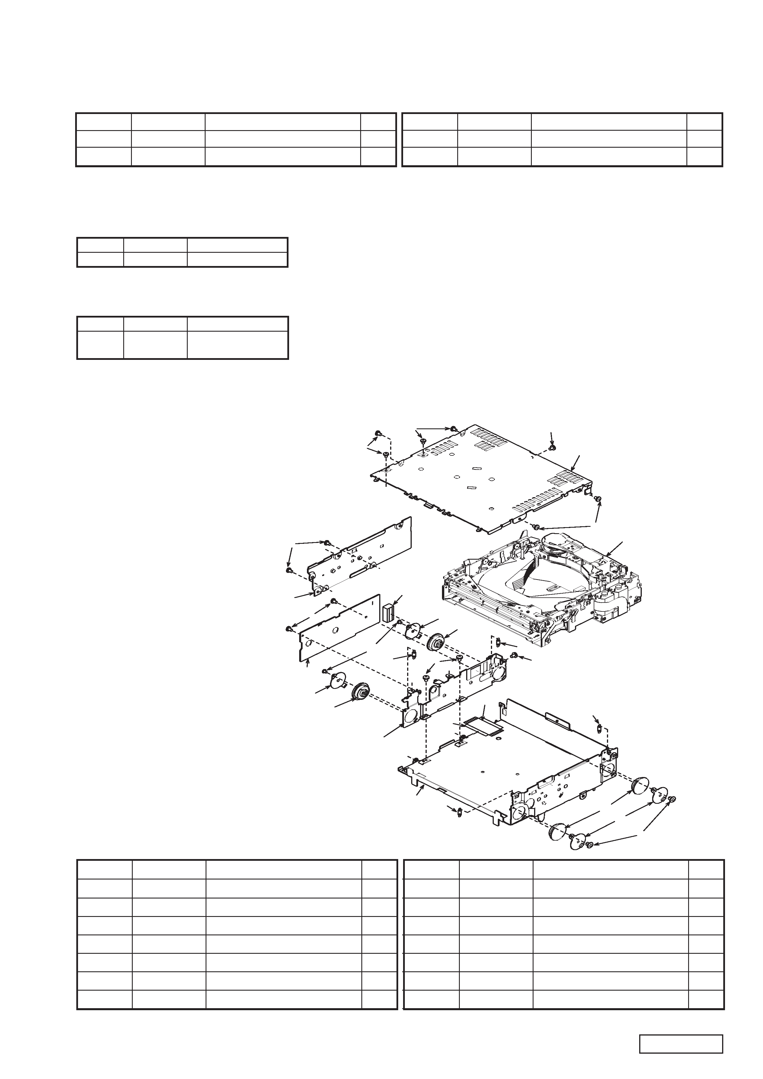
DEFFARENCE FROM ORIGINAL EXPLODED VIEW/PARTS LIST
Main section
*Refer to the figure on page 9 of original manual.The following parts were changed.
8
880-1728K
TUNER PACK
1
28
347-7359-01 EARTHSHEET
1
1
311-1864-24 LOWER CASE
1
2
331-3896-22 PWB-HOLDER
1
3
305-0334-20 SIDE CASE
1
4
310-1741-28 UPPERCASE
1
5
629-0083-01 DAMPER
4
6
620-1086-20 DAMPER-H-PLT
4
7
750-3491-00 FL-SPRING
4
NO.
PART NO.
DESCRIPTION
Q'TY
NO.
PART NO.
DESCRIPTION
Q'TY
31
929-0731-81 CD CHANGER MODULE
1
36
286-6469-13 SETPLATE
1
EXPLODED VIEW/PARTS LIST
CD changer module section:929-0731-81
8
-----------
CD PWB
1
9
716-1716-02 SCREW(M2x3)
14
10
HBS-561-100 FPC
1
11
716-3450-00 SCREW(M1.7x2)
4
12
-----------
CD CHANGER MECHANISM
1
13
347-6619-00 INSULATOR
1
14
345-8748-00 GASKET
1
NO.
PART NO.
DESCRIPTION
Q'TY
NO.
PART NO.
DESCRIPTION
Q'TY
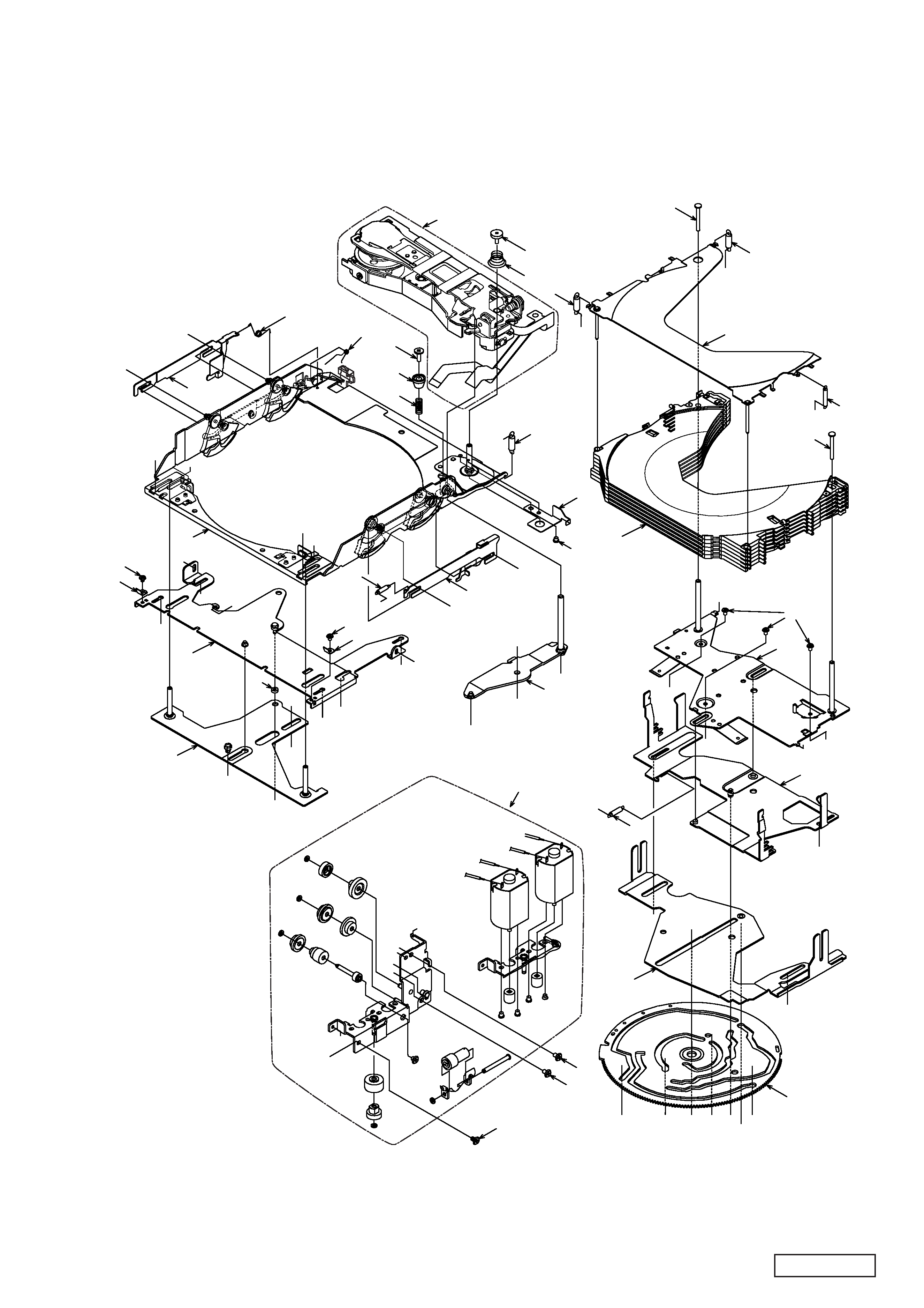
* No.12 : Refer to CD changer mechanism section.(page 4 - 6)
*Refer to the parts list on page 14 of original manual.The following parts were changed.
BL161
880-1728K
TUNER PACK
REF No.
PART No.
DESCRIPTION
Main PWB section(B2)
*Refer to the figure on page 14 and 15 of original manual.The following parts were changed.
IC402
052-3188-83 M30853FHGP
REF No.
PART No.
DESCRIPTION
J801
074-3010-60 10P SOCKET
DIFFERENCE FROM ORIGINAL ELECTRICAL PARTS LIST
Switch PWB section(B1)
background image
PN-2701B-B
- 4 -
1
85
67
41
2
36
32
64
67
22
22
60
62
24
29
22
60
25
47
45
63
9
51
72
31
60
6
62
69
28
55
69
55
88
7
38
63
62
69
76
46
69
53
7
89
87
62
33
18
81
44
5
8
68
49
20
62
82
68
58
34
69
70
71
42
69
J3
K6
K1
K5
L1
L2
L3
L4
J3
J9
L5
L6
L7
L8
K7 K8
J4
J8
J4
J6
J5
J1
I1
J9
L5
L7
J5
J6
L6
L8
J7
J8
J2
I2
J7
K5
K6
K7
K8
X5
A28
A8
A14
A26
A18
A4
A3
B3
A19
A9
C1
A1
A2
O1
A5
F1
X1
X2
X3
X4
A27
A10
A27
A15
A13
Q1
E6
T1
A17
A16
T2
E5
Q1
A26
A27
W1
O2
T4
X1
X2
X3
X4
Y1
Y3
Y2
Y4
S1
A30
E7
A6
O2
V1
O1
A13
M1
N1 N2
A12
A11
R1
U1
A7
A11
A12
N1
N2
M1
E1
A29
P1
E4
A21
A20
A14
A22
A28
U1
R1
A25
E2
A23
A24
S1
A25
L1
L2
L3
L4
27
52
62
35
35
62
26
23
35
30
62
A21
A20
A22
W1
V1
A24
A23
69
69
54
54
43
69
19
E3
P1
69
K1
62
86
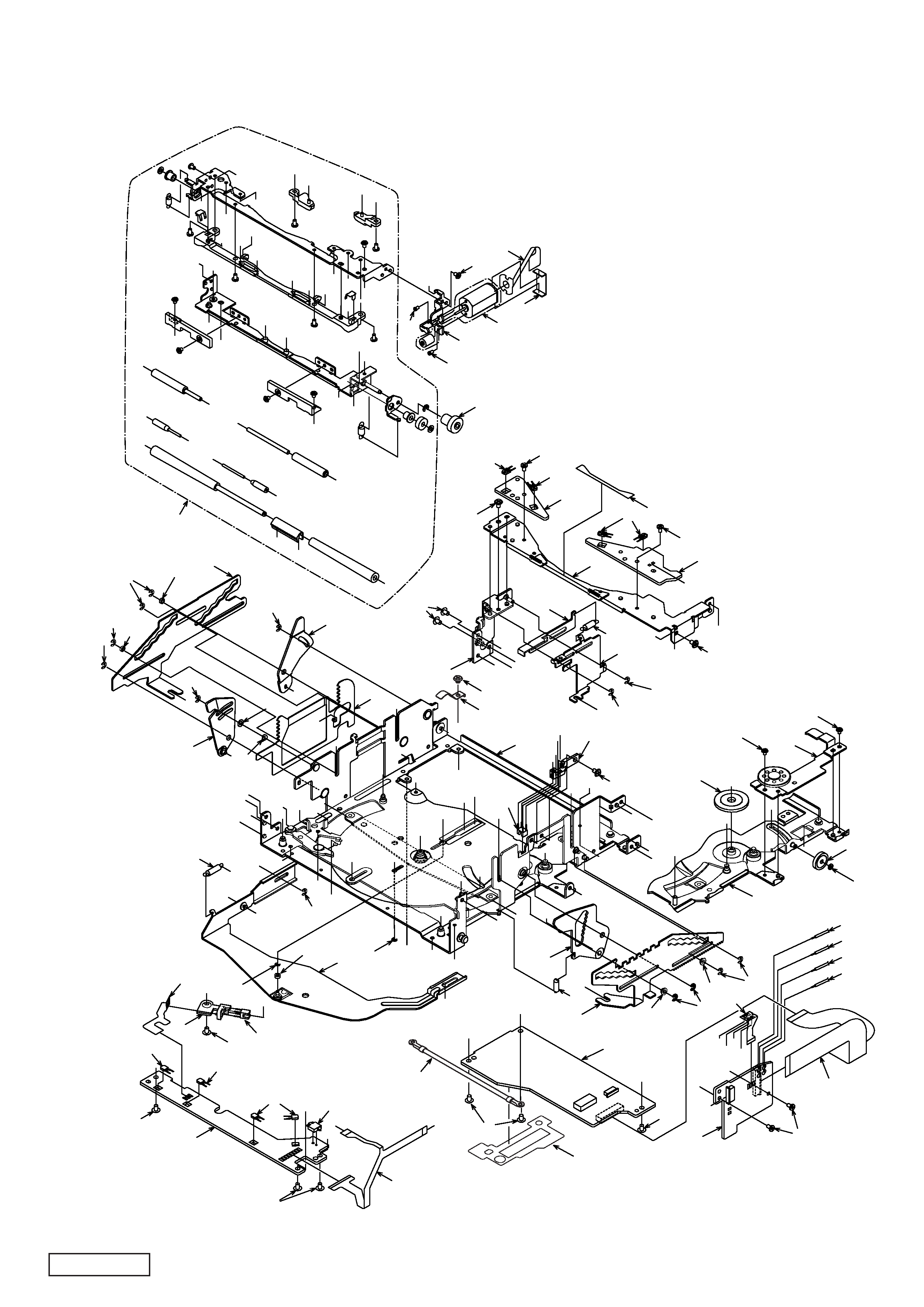
CD changer mechanism section
*Please see the parts list on page 6.
background image
PN-2701B-B
- 5 -
63
50
17
12
59
79
63
50
40
61
48
77
66
56
83
84
75
39
4
65
80
73
57
73
16
74
57
64
15
14
37
13
62
62
78
10
21
3
62
11
B1
I1
J1
E3
E1
E4
E8
I2
J2
A7
A8
A29
T3
G1
G2
G1
H1
G2
F1
D1
E8
A18
A6
A30
H1
B4
A10
A9
X5
C2
E7
E6
E5
E2
D1
C3
B2
T3
A17
T1
T2
A16
T4
A15
B1
B2
B4
A1
A2
A19 B3 A3
A4
A5
C2
C3
C1
Y2
Y1
Y4
Y3

Reviews

There are no reviews of this manual yet.