CANON POWERSHOT A40 Service Manual

Cover page of CANON POWERSHOT A40 Service Manual

Service Manual for CANON POWERSHOT A40, downloadable as a PDF file.

Manual details

  • Immediate download after payment.
  • Delivered as a PDF file.
  • The manual has 130 pages
  • File size: 12.68 MB
  • Available language versions: English
  • Different language versions may vary sligthly in file size and page count.

We guarantee that...

  • our manuals are complete,
  • the manual includes circuit diagrams,
  • our manuals are checked with antivirus,
  • We'll issue refund if the manual is damaged, incomplete or unreadable (our refund policy)

Sample pages

Thumbnail of page 1Thumbnail of page 2Thumbnail of page 3Thumbnail of page 4
Thumbnail of page 5Thumbnail of page 6Thumbnail of page 7Thumbnail of page 8
Thumbnail of page 9
background image
background image
background image
Application
This manual has been issued by Canon Inc. for qualified persons to learn technical theory, and
repair of the products.
Corrections
This manual could include typographical errors or technical inaccuracies due to improvements or
changes in the products. When changes occur in applicable products or in the content of this manual,
Canon will release service manual report as the need arises. In the event of major changes in the
contents of this manual over a long or short period, Canon may issue new editions of this manual.
The following paragraph does not apply to any countries where such provisions are inconsistent
with local law.
Trademarks
The product names and company names described in this manual are the registered trademarks of
the individual companies.
Copyright
This manual is copyrighted with all rights reserved. Under the copyright laws, this manual may not
be copied, reproduced, published (including on the World Wide Web) or translated into another
language, in whole or in part, without the written consent of Canon Inc..
Copyright © 2002 by Canon Inc.
CANON INC.
Digital Imaging Products Service Dept.
30-2, Shimomaruko 3-Chome, Ohta-ku,
Tokyo 146-8501, Japan
background image
SAFETY PRECAUTIONS
The following precautions should be observed when servicing.
1.
Since many parts in the unit have special safety-related characteristics, always use genuine CANON replacement parts.
Especially critical parts in the power circuit block should not be replaced with other makes.
Critical parts are marked with ! in the schematic diagrams.
2.
When servicing, observe the original lead dress. If a short circuit is found, replace all parts which have been overheated or damaged
by the short circuit.
3.
After servicing, see to it that all the protective devices such as insulation barriers, insulation papers shields are properly installed.
4.
After servicing, make the following leakage current checks to prevent the customer from being exposed to shock hazards.
4-1 Leakage Current Cold Check
1) Unplug the AC cord and connect a jumper between the two prongs on the plug.
2) Measure the resistance value, with an ohmmeter, between the jumpered AC plug and each exposed metallic cabinet part
on the equipment such as screwheads, connectors, control shafts, etc. When the exposed metallic part has a return path to
the chassis, the reading should be between 1M
and 5.2M. When the exposed metal does not have a return path to the
chassis, the reading must be
.
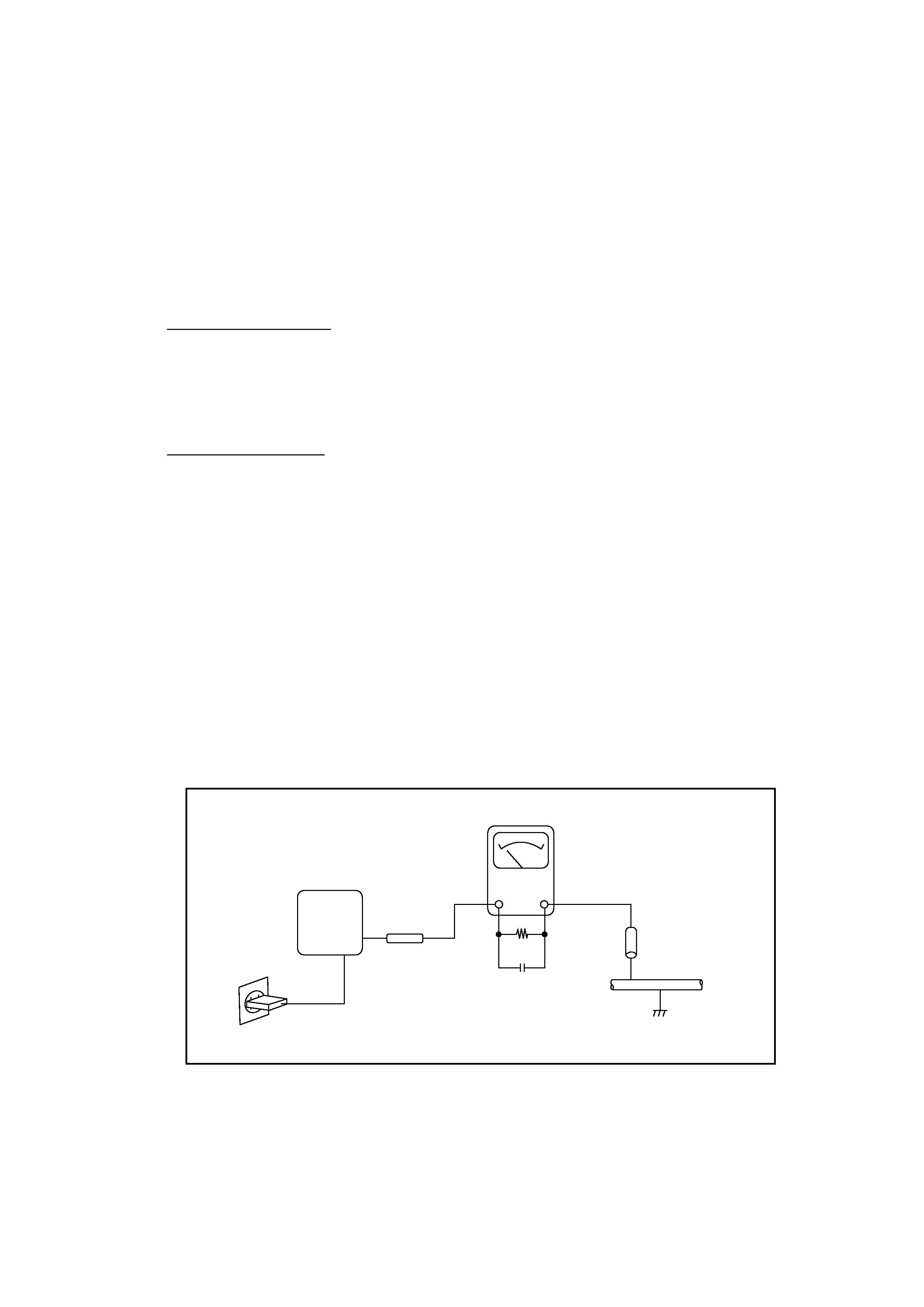
4-2 Leakage Current Hot Check
1) Plug the AC cord directly into the AC outlet. Do not use an isolation transformer for this check.
2) Connect a 1.5K
10 watt resistor, paralleled by 0.15µF capacitor, between each exposed metallic parts on the unit and a
good earth ground such as a water pipe, as shown in the figure below.
3) Use an AC voltmeter, with 1000
/volt or more sensitivity, to measure the potential across the resistor.
4) Check all exposed metallic parts of the cover (Cable connection, Handle bracket, metallic cabinet.
Screwheads, Metallic overlays, etc), and measure the voltage at each point.
5) Reverse the AC plug in the AC outlet and repeat each of the above measurements.
6) The potential at any point should not exceed 0.75V RMS.
A leakage current tester (FLUKE MODEL : 8000A equivalent) may be used to make the hot checks.
Leakage current must not exceed 0.5 milliamp.
In case a measurement is outside of the limits specified, there is a possibility of a shock hazard, and corrective action must
be taken before returning the instrument to the customer.
Water pipe
(Earth Ground)
1.5K
0.15
µF
Test all
exposed
metal parts
Figure. 1 Leakage Current Hot Check
AC OUTLET
AC VOLTMETER
DEVICE
UNDER
TEST
background image
1
Development Background
1-1 Development Objectives --------------------------------------------------------------------------------------------------- 1-1
1-2 Product Concept ------------------------------------------------------------------------------------------------------------- 1-1
1-3 Design Concepts ------------------------------------------------------------------------------------------------------------- 1-3
1-4 Spec. comparison between new and prior models ---------------------------------------------------------------------- 1-4
2
Features*
2-1 High Image Quality --------------------------------------------------------------------------------------------------------- 1-6
2-2 Full Features / Operation ease --------------------------------------------------------------------------------------------- 1-7
2-3 Accessories and Software -------------------------------------------------------------------------------------------------1-10
3
Exterior
3-1 Exterior Photos ------------------------------------------------------------------------------------------------------------ 1-13
3-2 6-dimensional diagram --------------------------------------------------------------------------------------------------- 1-15
3-3 Nomenclature ---------------------------------------------------------------------------------------------------------------1-16
3-4 UI Display -------------------------------------------------------------------------------------------------------------------1-17
4
Specifications
4-1 Camera Specifications -----------------------------------------------------------------------------------------------------1-21
4-2 System Requirement -------------------------------------------------------------------------------------------------------1-27
4-3 Accessory Specifications ------------------------------------------------------------------------------------------------- 1-28
5 System
5-1 Accessories' Compatibility -----------------------------------------------------------------------------------------------1-29
5-2 System Diagram ------------------------------------------------------------------------------------------------------------1-31
* Please refer to Technical Guidance for PowerShot A20/A10 (TI-00906) P.5--P.18
CHAPTER 1. GENERAL DESCRIPTION
OF PRODUCT
CONTENTS
background image

Reviews

There are no reviews of this manual yet.