ORDER NO.
PIONEER CORPORATION 4-1, Meguro 1-chome, Meguro-ku, Tokyo 153-8654, Japan
PIONEER ELECTRONICS (USA) INC. P.O. Box 1760, Long Beach, CA 90801-1760, U.S.A.
PIONEER EUROPE NV Haven 1087, Keetberglaan 1, 9120 Melsele, Belgium
PIONEER ELECTRONICS ASIACENTRE PTE. LTD. 253 Alexandra Road, #04-01, Singapore 159936
PIONEER CORPORATION 2002
RRV2602
T-ZZM MAY. 2002 Printed in Japan
SPEAKER SYSTEM
FOR PRECAUTION OF
REASSEMBLY AND DISASSEMBLY
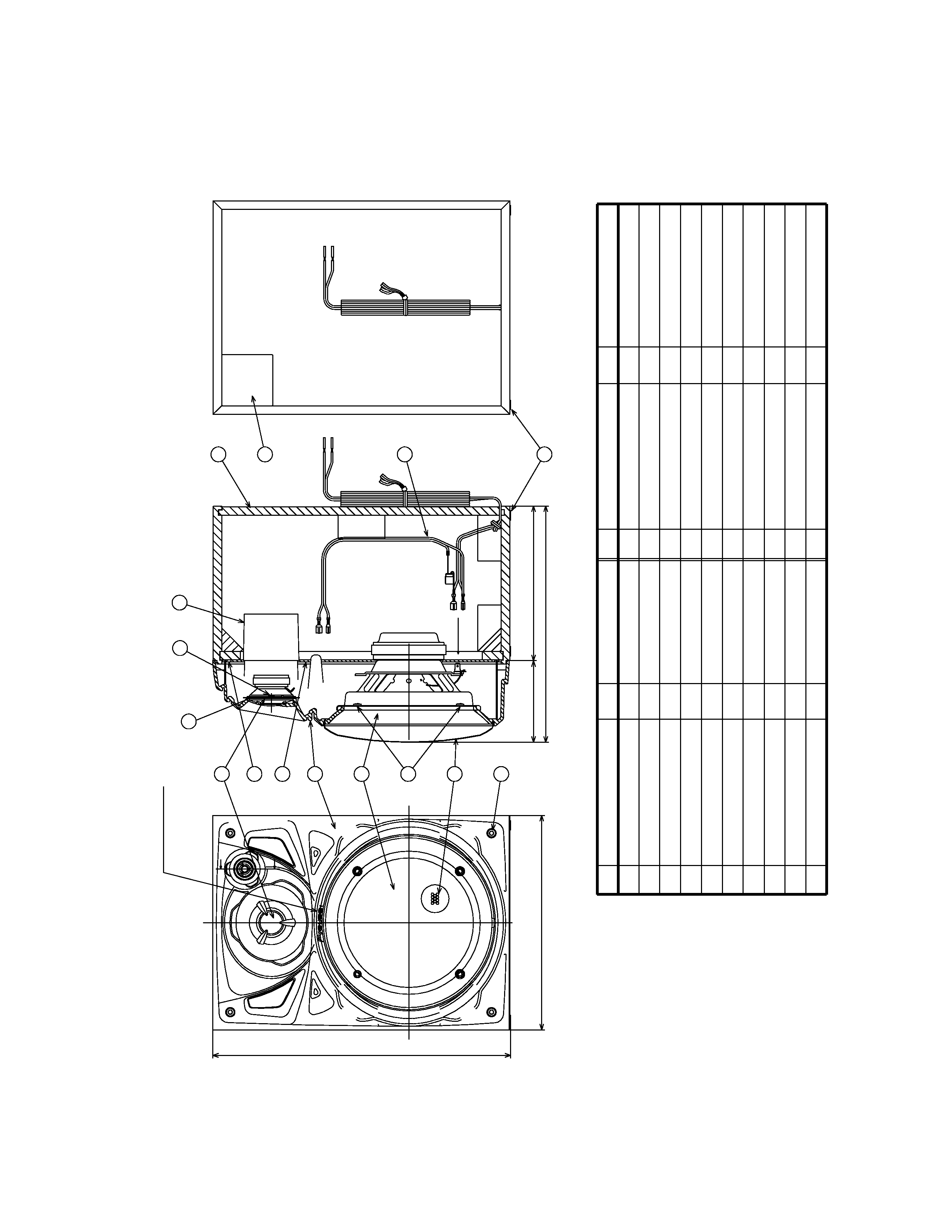
The cosmetic baffle assy is attached to the cabinet by 4 external
screws. To detach the cosmetic baffle assy, loosen these
screws. Then carefully disconnect the wires of the woofer and
tweeter mounted on the cosmetic baffle assy. To attach the cos-
metic baffle assy, replace it on the cabinet correctly and secure
with 4 screws.
The woofer is attached to the cosmetic baffle assy by 4 internal
screws. To detach it, unfasten these screws. When attaching it,
face its terminal downward.
The tweeter is attached to the cosmetic baffle assy by 2 internal
screws. To detach it, loosen these screws. When attaching it,
face its terminal downward.
S-A390L
XJI/E