ONKYO DVCP802 Service Manual

Cover page of ONKYO DVCP802 Service Manual

Service Manual for ONKYO DVCP802, downloadable as a PDF file.

We also have owner's manual to this model.

Manual details

  • Immediate download after payment.
  • Delivered as a PDF file.
  • The manual has 139 pages
  • File size: 13.23 MB
  • Available language versions: English
  • Different language versions may vary sligthly in file size and page count.

We guarantee that...

  • our manuals are complete,
  • the manual includes circuit diagrams,
  • our manuals are checked with antivirus,
  • We'll issue refund if the manual is damaged, incomplete or unreadable (our refund policy)

Sample pages

Thumbnail of page 1Thumbnail of page 2Thumbnail of page 3Thumbnail of page 4
Thumbnail of page 5Thumbnail of page 6Thumbnail of page 7Thumbnail of page 8
Thumbnail of page 9
background image
DV-CP802
SERVICE MANUAL
SERVICE MANUAL
Black and Silver models
120V AC,60Hz
CDD1N
Ref. No. 3798
062004
DVD CHANGER
MODEL
DV-CP802
RC-542DV
ON
STANDBY
SEARCH LAST M MEMORY CHAIN MODE
REPEAT
A-B
RANDOM
DISPLAY
MENU
SETUP
TOP MENU
RETURN
AUDIO
ANGLE SUBTITLE ZOOM
DISC
1
DISC
2
DISC
3
DISC
4
DISC
5
DISC
6
DISC SKIP
DIMMER
RC-542DV
STEP/SLOW
CLEAR
OPEN/
CLOSE
PROGRESSIVE
ENTER
+10
0
123
456
789
STANDBY/ON
STANDBY
SAFETY-RELATED COMPONENT
WARNING!!
COMPONENTS IDENTIFIED BY MARK
ON THE
SCHEMATIC DIAGRAM AND IN THE PARTS LIST ARE
CRITICAL FOR RISK OF FIRE AND ELECTRIC SHOCK.
REPLACE THESE COMPONENTS WITH ONKYO
PARTS WHOSE PART NUMBERS APPEAR AS SHOWN
IN THIS MANUAL.
MAKE LEAKAGE-CURRENT OR RESISTANCE
MEASUREMENTS TO DETERMINE THAT EXPOSED
PARTS ARE ACCEPTABLY INSULATED FROM THE
SUPPLY CIRCUIT BEFORE RETURNING THE
APPLIANCE TO THE CUSTOMER.
background image
SPECIFICATION
DV-CP802
DV-CP802
SpeciÞcations and features subject to change without notice.
Signal System
NTSC
Composite Video Output/Impedance
1.0 V (p-p)/75
negative sync, RCA/phono
S-Video Output/Impedance
Y: 0.7 V (p-p)/75
negative sync, 4-pin mini DIN
C: 0.286 V (p-p)/75
Component Video Output/Impedance
Y: 1.0 V(p-p)/75
PB/PR: 0.7 V (p-p)/75
RCA/phono
Frequency
Response
DVD-Audio
4 Hz-50 kHz (192 kHz)
DVD Linear Sound
4 Hz-44 kHz (96 kHz)
4 Hz-22 kHz (48 kHz)
Audio CD
4 Hz-20 kHz (44.1 kHz)
S/N ratio
110 dB
Audio Dynamic Range
98 dB
THD (Total Harmonic Distortion)
0.005 % (1 kHz)
Wow and Flutter
Below threshold of measurability
Audio Output (Digital/Optical)
-22.5 dBm
Audio Output/Impedance (Digital/Coaxial)
0.5 V p-p/75
Audio Output/Impedance (Analog)
2.0 V (rms)/600
Power Supply
AC 120 V, 60 Hz
Power Consumption
21 W
Standby Power Consumption
0.6 W
Dimensions (W x H x D)
435 x 131 x 432 mm
17-1/8 x 5-3/16 x17 inches
Weight
7.3 kg
16.1 lbs.
Operation Condition Temperature
5-35 C (4-95 F)
Disc Compatibility
DVD-VIDEO, DVD-AUDIO, CD, CD-R, CD-RW, SACD, MP3,
DVD-R, DVD-RW, JPEG, VCD
Disc that have not been property Þnalized may only be partially
playable or not playable at all.
background image
SERVICE PROCEDURES-1
DV-CP802
WARNING
RISK OF ELECTRIC SHOCK
DO NOT OPEN
RISQUE DE CHOC ELECTRIQUE
NE PAS
OUVRIR
AVIS
"CLASS 1 LASER
PRODUCT"
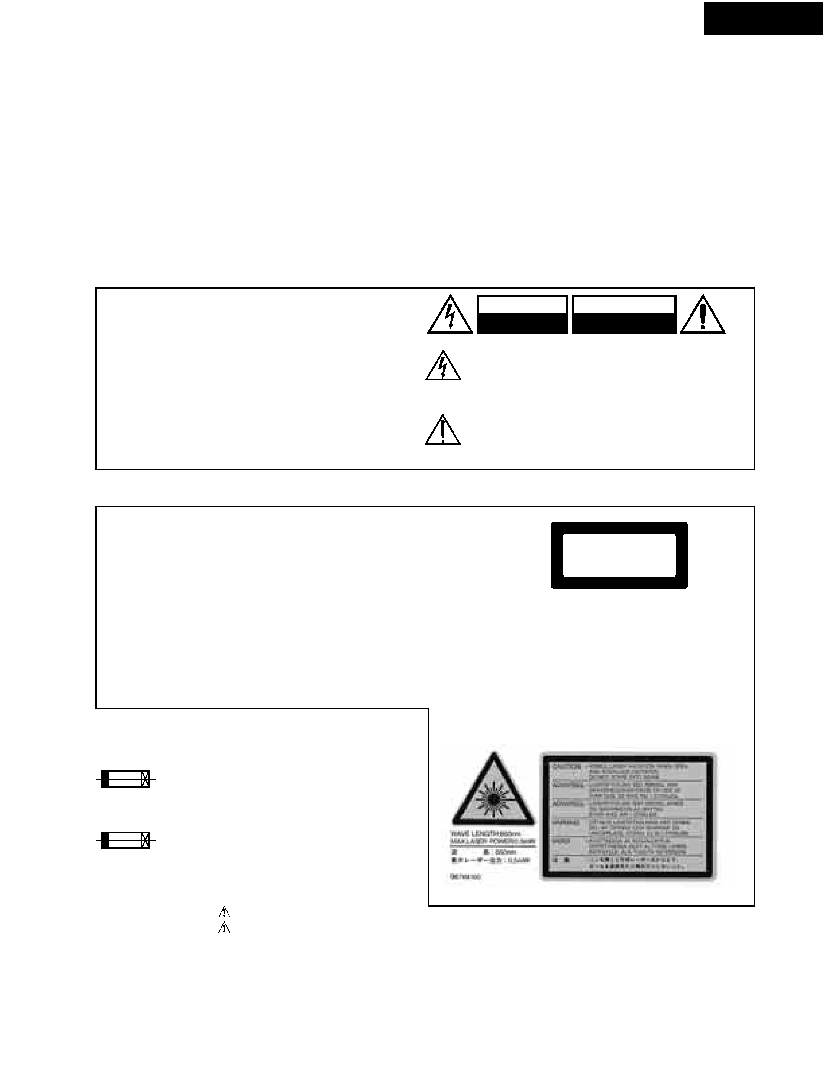
PROTECTION OF EYES FROM LASER BEAM DURING SERVICING
WARNING
LASER WARNING
This set employs a laser. Therefore, be sure to follow
carefully the instructions below when servicing.
1. Replacing the fuses
SERVICE PROCEDURE
This symbol located near the fuse indicates that the
fuse used is show operating type, For continued protection against
fire hazard, replace with same type fuse , For fuse rating, refer to
the marking adjest to the symbol.
Ce symbole indique que le fusible utilise est e lent.
Pour une protection permanente, n'utiliser que des fusibles de meme
type. Ce demier est indique la qu le present symbol est apposre.
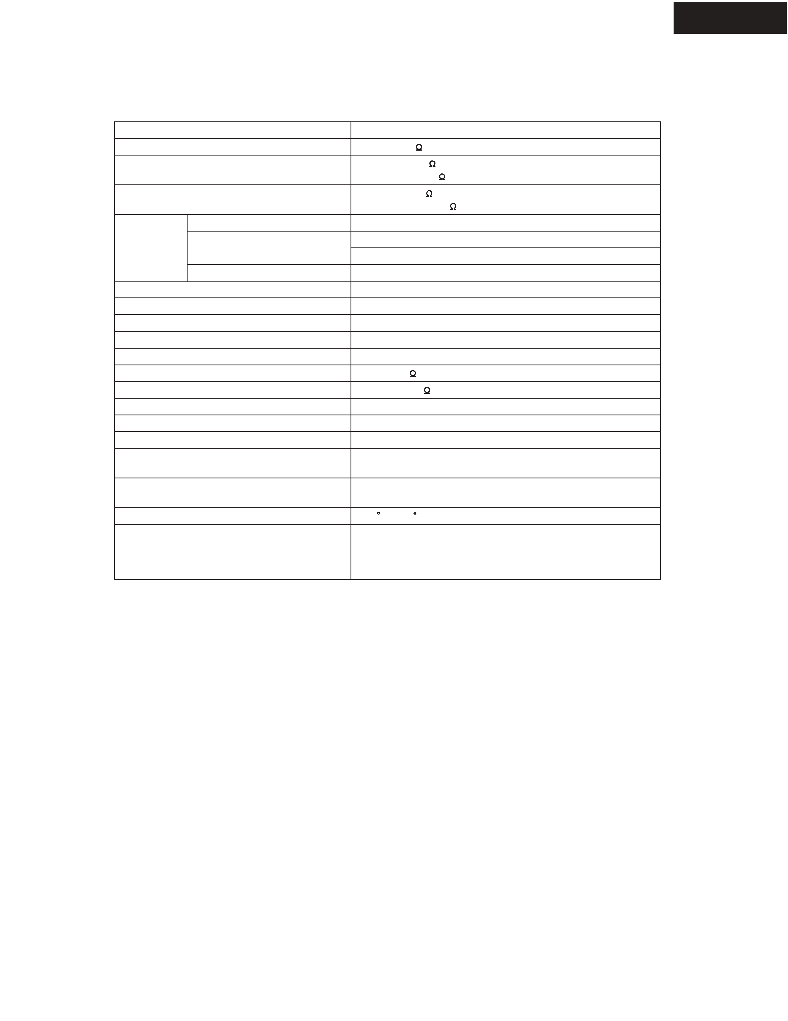
Laser Diode Properties
Wavelength: 650/780nm (DVD/CD)
SERVICE WARNING : DO NOT APPROACH THE
LASER EXIT WITH THE EYE TOO CLOSELY.
IN CASE IT IS NECESSARY TO CONFIRM LASER
BEAM EMISSION, BE SURE TO OBSERVE FROM
A DISTANCE OF MORE THAN 30cm FROM THE
SURFACE OF THE OBJECTIVE LENS ON THE
OPTICAL PICKUP BLOCK.
WARNING!!
WARNING:
TO REDUCE THE RISK OF FIRE OR ELECTRIC SHOCK,
DO NOT EXPOSE THIS APPLIANCE TO RAIN OR
MOISTURE.
CAUTION:
TO REDUCE THE RISK OF ELECTRIC SHOCK, DO NOT
REMOVE COVER (OR BACK). NO USER-SERVICEABLE
PARTS INSIDE. REFER SERVICING TO QUALIFIED
SERVICE PERSONNEL.
The lightning flash with arrowhead symbol, within
an equilateral triangle, is intended to alert the user to
the presence of uninsulated "dangerous voltage" within
the product's enclosure that may be of sufficient magnitude
to constitute a risk of electric shock to persons.
The exclamation point within an equilateral triangle is
intended to alert the user to the presence of important
operating and maintenance (servicing) instructions in the
literature accompanying the appliance.
This unit contains a semiconductor laser system and is classified
as a "CLASS 1 LASER PRODUCT". So, to use this model
properly, read this Instruction Manual carefully. In case of any
trouble, please contact the store where you purchased the unit.
To prevent being exposed to the laser beam, do not try to open
the enclosure.
VISIBLE LASER RADIATION WHEN OPEN AND INTERLOCK
FAILED OR DEFEATED. DO NOT STARE INTO BEAM.
THIS PRODUCT UTILIZES A LASER. USE OF CONTROLS
OR ADJUSTMENTS OR PERFORMANCE OF PROCEDURES
OTHER THAN THOSE SPECIFIED HEREIN MAY RESULT IN
HAZARDOUS RADIATION EXPOSURE.
The label on the right
is applied on the rear
panel except for USA
and Canadian
models.
1.This unit is a CLASS 1 LASER PRODUCT and employs a
laser inside the cabinet.
2.To prevent the laser from being exposed, do not remove
the cover. Refer servicing to qualified personnel.
CAUTION:
CAUTION:
LASER BEAM CAUTION LABEL
REF. NO.
PART NO.
DESCRIPTION
F101
5120-0130-0 or
1.6A-UL/T-237 <CDD1N>
5120-1000-0
1.6A-T/UL-ST2 <CDD1N>
North American area
background image
SERVICE PROCEDURES-2
DV-CP802
2. Safety-check out
(Only U.S.A. model)
After correcting the original service problem perform the
following safety check before releasing the set to the customer
Connect the insulating-resistance tester between the plug of
power supply cord and terminal GND on the back panel.
Specifications: More than 10M ohm at 500V
INITIALIZING
Factory-shipped condition
Push button "ON" (Mechanical SW)
Press the [STOP] and [STANDBY] same time with NO DISC condition.
Push button "STANDBY".
After display "COMPLETE".
REMOVE THE SOLDER OF LASER DIODE SHORT
When replace the mechanism or DVD main PC board.
Shotting the solder of Shot-circuit land. (2 positions)
background image
PANEL VIEWS-1
FRONT PANEL
DV-CP802
STANDBY/ON
STANDBY
2
3
5
7
8
10
11
1
4
6
9
12
13
14 15
16
17
18
19 20
DISC SELECT 1-6 buttons
These buttons are used to select discs. Playback
starts automatically when discs are selected with
these buttons
11
Disc tray
The disc tray has six bays for loading up to six discs.
12
Disc tray light
This light illuminates the disc tray. It comes on
when the DV-CP802 is turned on, and is brighter
while the disc tray is open.
13
DISC SKIP button
This button is used to select the disc bays (i.e., rotate
the disc tray) when loading or removing discs, and
to select discs for playback.
14
Previous [
] button
This button is used to select the previous chapter or
track. During playback it selects the beginning of
the current chapter or track.
15
Next [
] button
This button is used to select the next chapter or
track.
16
PAUSE [ ] button
This button is used to pause playback.
17
CHAIN MODE button
This button is used with the Chain mode function.
18
STOP [ ] button
This button is used to stop playback.
19
PLAY/ENTER [ ] button
This button is used to start playback and to cancel
fast forward and fast reverse. It's also used to start
Chain mode playback.
20
STANDBY/ON button
This button is used to set the DV-CP802 to On or
Standby.
Don't turn on the power until you've completed and
double checked all of your connections.
1
STANDBY indicator
This indicator lights up when the DV-CP802 is in
Standby mode.
2
VIDEO CIRCUIT OFF button & indicator
This button is used to turn off all of the internal
video circuitry, eliminating the possibility of interference
when playing audio-only discs. The button
lights up when the video circuitry is turned off.
3
LAST MEMORY button
This button is used with the Last Memory function.
4
REPEAT button
This button is used with the Repeat function.
5
DIMMER button
This button is used to adjust the display brightness.
6
DISPLAY button
This button is used to display information about the
current disc, title, chapter, or track, including the
elapsed time, remaining time, total time, and so on.
7
Display
8
Remote control sensor
This sensor receives control signals from the remote
controller.
9
Open/Close [ ] button
This button is used to open and close the disc tray.
10

Reviews

There are no reviews of this manual yet.